Rheology
Rheology is the relation between the stress a material carries and the rate at which it deforms. In a mantle-convection model it enters through one field, the viscosity
Physical background
Why solid rock flows
The mantle is solid. It transmits shear waves and, over seconds to years, it deforms elastically. Over millions of years it flows, because at temperatures above roughly half its melting temperature a crystalline rock deforms by thermally activated creep. Atoms diffuse through and around the grains, and lattice defects (dislocations) glide and climb through the crystals. Each of these processes produces a strain rate that grows with stress and very steeply with temperature (Karato 2008; Turcotte & Schubert 2014).
The time scale that separates the elastic from the viscous response is the Maxwell time,
A creeping rock is described by an effective viscosity, the ratio of the deviatoric stress to twice the strain rate,
where
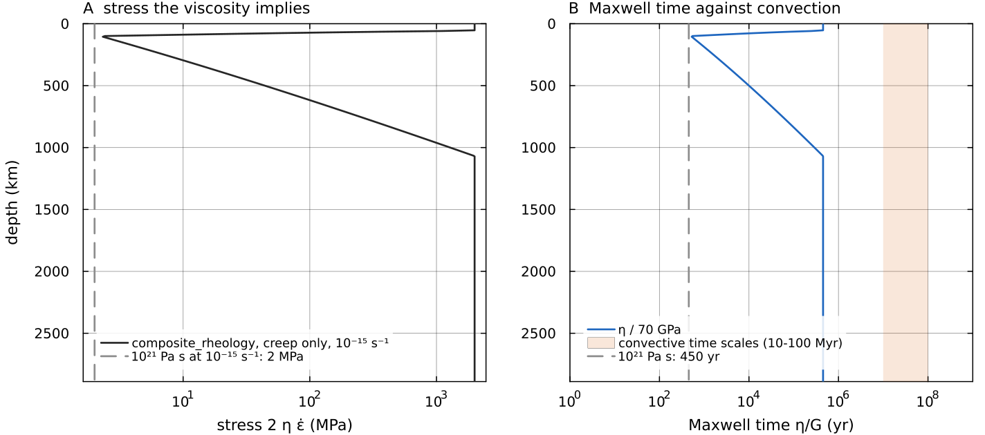
Creep viscosity from composite_rheology (yield branch switched off, default clamps) along the code's geotherm, an adiabat of 1600 K potential temperature below a 100 km conductive lid, at docs/scripts/fig_rheology_sections.jl.
Deformation mechanisms
Laboratory experiments on olivine, the dominant upper-mantle mineral, identify several creep mechanisms (Karato & Wu 1993; Hirth & Kohlstedt 2003). They differ in how the strain rate depends on stress
| mechanism | strain rate scales as | viscosity | where it matters |
|---|---|---|---|
| diffusion creep | Newtonian, grain-size sensitive | hot mantle, small grains, low stress | |
| dislocation creep | strain-rate weakening, grain-size insensitive | higher stress, larger grains, upper mantle and lid base | |
| grain-boundary sliding | both stress and grain-size sensitive | intermediate conditions | |
| Peierls (low-temperature) plasticity | exponential in | very strongly stress dependent | cold lithosphere at high stress |
| frictional sliding and fracture | stress set by pressure, not by rate | perfectly plastic | the brittle upper lithosphere |
All the thermally activated mechanisms share an Arrhenius dependence
Mechanisms that operate side by side in the same grains act in parallel. Each accommodates part of the deformation at the same stress, so their strain rates add, and at a common stress their viscosities combine harmonically,
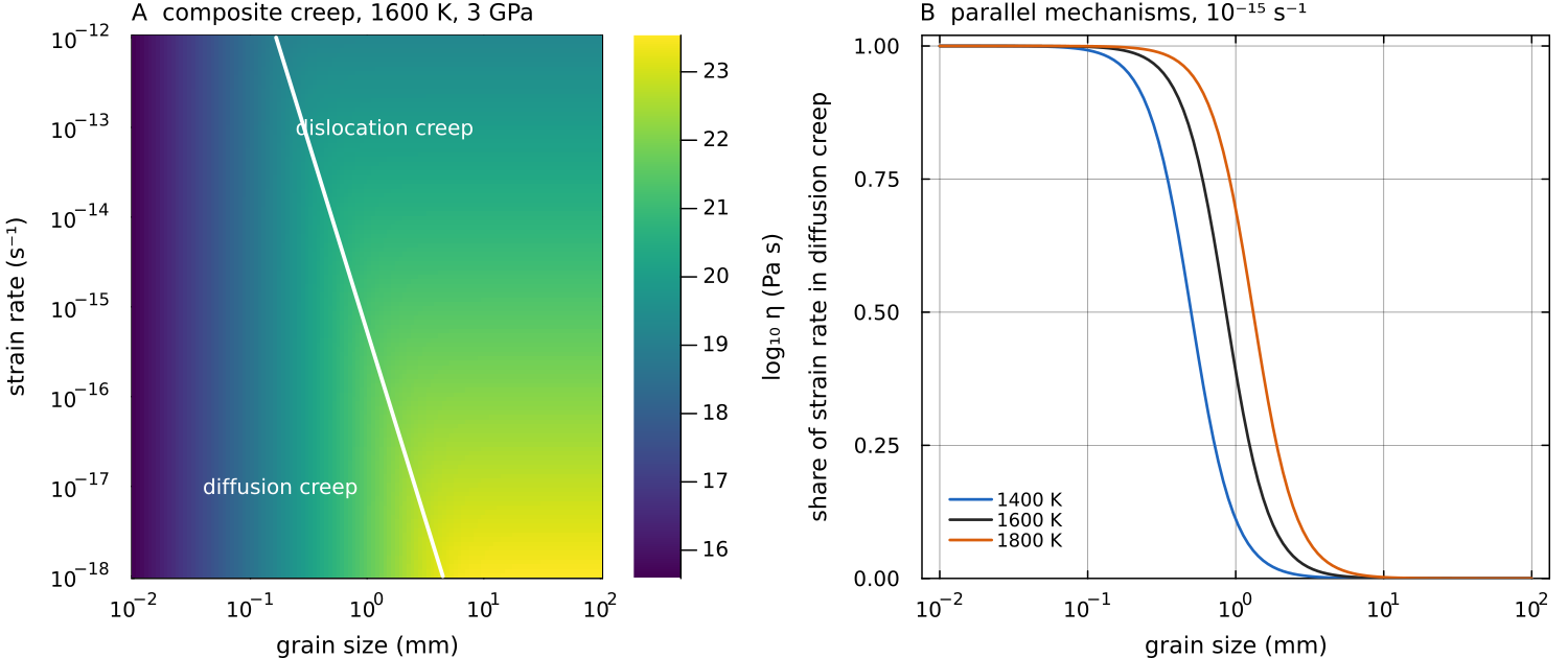
The default reference-viscosity creep laws of composite_rheology at 1600 K and 3 GPa, with the grain size entering diffusion creep (cfg.evolveGrainSize = true). Left: the viscosity of the parallel combination; the white line is where diffusion and dislocation creep are equally strong. Right: the fraction of the strain rate carried by diffusion creep, docs/scripts/fig_rheology_sections.jl.
Near the surface a different limit applies. Cold rock cannot creep fast enough, and it fails by fracture and frictional sliding instead, at a stress that rises with the confining pressure and hardly depends on the strain rate. Laboratory friction coefficients of 0.6 to 0.85 hold for most rock types (Byerlee 1978). The strength of the lithosphere at any depth is the smaller of the brittle and the ductile strength, the "strength envelope" reviewed by Kohlstedt, Evans & Mackwell (1995). Convection models need effective friction coefficients well below Byerlee's values to break the lid into plates (Moresi & Solomatov 1998; Tackley 2000), which is commonly attributed to pore-fluid pressure and to weak, pre-existing faults.
How strongly the viscosity varies
The Arrhenius factor makes temperature the dominant control. Differentiating it gives
| change | diffusion creep ( | dislocation creep ( |
|---|---|---|
| temperature change for a factor 10 | 163 K | 318 K (the exponent is divided by |
| cooling from 1600 K to 1000 K, at | ||
| pressure from 0 to 5 GPa | ||
| strain rate | no change | |
| grain size | no change |
A cold lid is therefore many orders of magnitude stiffer than the interior. A convenient measure of this sensitivity is the Frank-Kamenetskii parameter
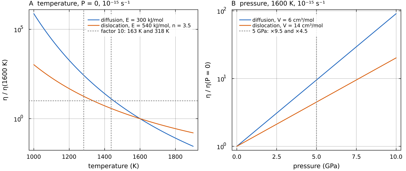
The default diffusion and dislocation laws of composite_rheology, each alone and normalised to its value at the reference state, at a fixed strain rate of docs/scripts/fig_rheology_sections.jl.
Typical values
| quantity | value | source |
|---|---|---|
| Earth, average upper-mantle viscosity | Mitrovica & Forte (2004) | |
| Venus, interior viscosity inferred from stagnant-lid scaling | Solomatov & Moresi (1996) | |
| mantle strain rates | of order | estimate above |
| rock friction coefficient | 0.6 to 0.85 | Byerlee (1978) |
| olivine activation energy | 300 to 540 kJ/mol | Karato & Wu (1993); Hirth & Kohlstedt (2003) |
Venus has no plate tectonics today, and its surface is dry. Mackwell, Zimmerman & Kohlstedt (1998) found dry diabase, a proxy for the Venus crust, to be much stronger than earlier wet-rock data suggested, which favours a strong lid; this is why the crustal presets of the Flow laws page include their law.
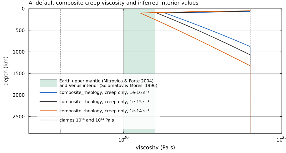
Creep viscosity of composite_rheology with default parameters (yield branch off) on the geotherm of the figures above, at three strain rates, against the docs/scripts/fig_rheology_sections.jl.
How MILEVA builds the viscosity
The viscosity main_SphCon.jl. There are two paths, chosen by cfg.useCompositeRheology:
| path | cfg.useCompositeRheology | entry point | depends on |
|---|---|---|---|
| simple | false (default) | compute_viscosity (physics/compute_viscosity.jl), optionally overwritten by frank_kamenetskii_viscosity! (utils/fk_viscosity.jl) | |
| composite | true | composite_rheology (physics/composite_rheology.jl) |
Both end with the clamp cfg.eta_min = 1e18, cfg.eta_max = 1e24 Pa s by default). Optional modifiers (visco-elasto-plasticity, damage) are then applied on top, in that order.
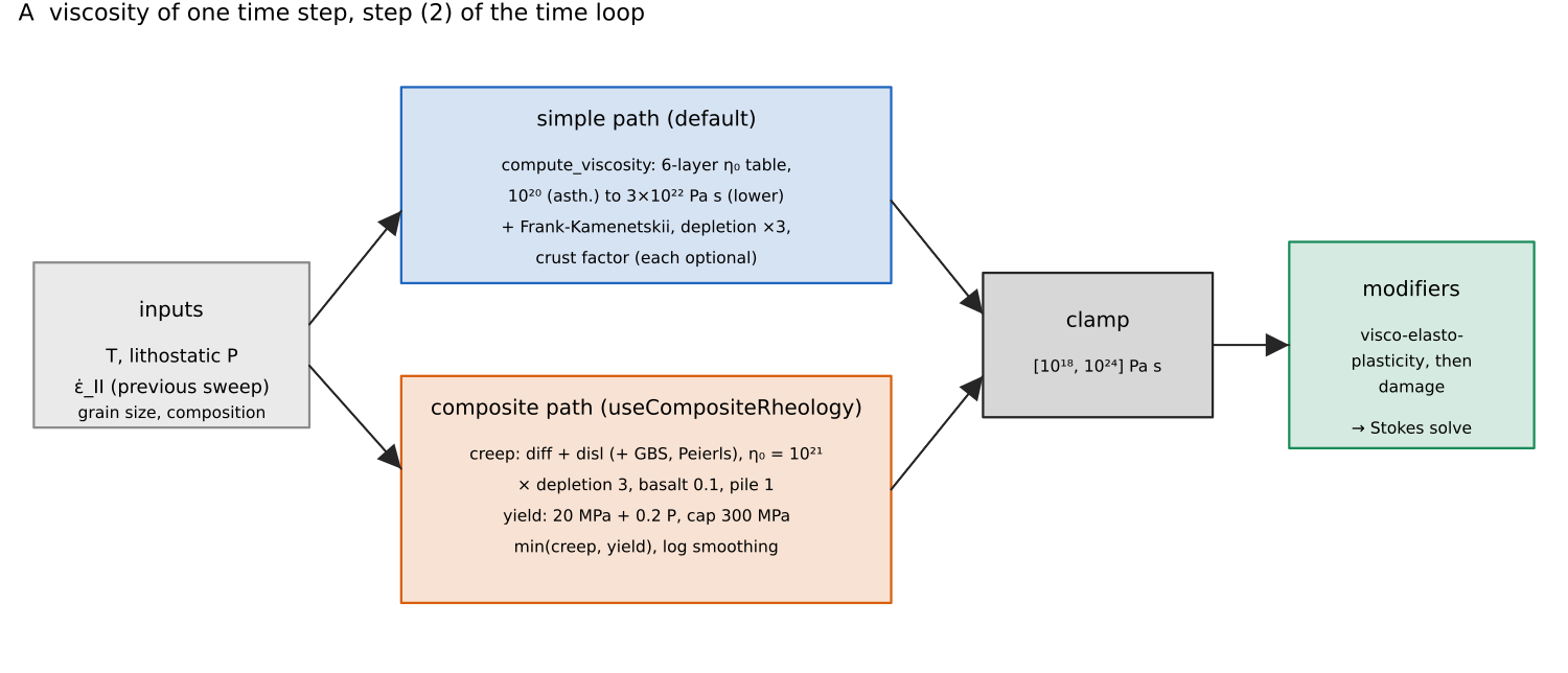
The two paths that build the viscosity in step (2) of the time loop, with the default values each stage uses. Schematic; the numbers are the defaults of MaterialProperties and SimConfig. Script: docs/scripts/fig_rheology_sections.jl.
The strain-rate invariant used throughout is
in 2-D (the compute_strain_rate, utils/compute_strain_rate.jl). The 2-D routine returns a raw and a spatially smoothed invariant; the rheology uses the smoothed one, the dissipation diagnostic the raw one. compute_strain_rate guards the square root with a floor of composite_rheology floors
Simple path: layered Arrhenius
compute_viscosity evaluates a pressure-scaled Arrhenius law on a six-layer prefactor table:
where mat.E_act_scale and mat.V_act_scale are in kelvin and kelvin per pascal (an activation energy and volume divided by the gas constant), mat.T_ref, and get_layer(mat, r) (config/MaterialProperties.jl):
| layer | radius range | prefactor field | default (Pa s) |
|---|---|---|---|
| 1, D″ | R_Dprime | Dprime_eta0 | |
| 2, lower mantle | R_lower | lower_eta0 | |
| 3, transition zone | R_trans | trans_eta0 | |
| 4, upper mantle | R_upper | upper_eta0 | |
| 5, asthenosphere | R_asth | asth_eta0 | |
| 6, lithosphere | above | lith_eta0 |
The layer radii default to Earth values and must be set for another planet. Setting all six prefactors equal and
The 3-D method of compute_viscosity uses the same table with the exponent mat.V_act_scale term.
This path is a prescribed, Newtonian viscosity. It depends on temperature and depth but not on stress, grain size or strain history, which makes it the natural choice for benchmarks and for isolating thermal effects. Because mat.E_act_scale = 200 K is far smaller and gives an almost depth-layered viscosity; between 1600 K and 1000 K it changes
After compute_viscosity, the simple path applies, in order:
- Frank-Kamenetskii (
cfg.useFrankKamenetskii), which overwritesentirely with one of two forms selected by cfg.fkForm:
with fk_eta_ref, fk_E, fk_T_ref and fk_theta. Both are approximations to the Arrhenius law that keep the viscosity contrast bounded and controllable. The simple form is the exponential approximation named after Frank-Kamenetskii, linear in
Depletion stiffening (
cfg.useDepletionStiffening):with = mat.harzburgite_eta_factor(default 3) and= cfg.fertileFraction(default 0.30), the same factor the composite path applies.Crust factor (2-D,
cfg.crustViscosityFactor): , with the crust fraction defined in Buoyancy and composition. Yield cap (
cfg.useSimpleYield, exercised in 2-D only):simple_yield!inphysics/compute_viscosity.jlcaps the stress at the Drucker-Prager yield stress of the composite path,with the same MaterialPropertiesfields, by. Unlike the composite path it acts at every temperature ( cfg.yieldMinTis not applied). The viscosity is then nonlinear, so the time loop iterates it with the solve (Nonlinear iteration); the stagnant-lid example uses it with a depth-independent. validate!refuses it together withuseCompositeRheologyor a radial viscosity file.
Each step re-clamps to
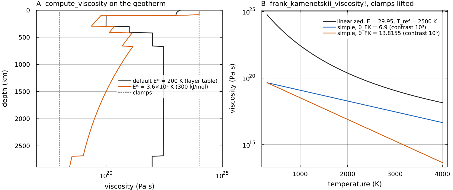
Left: compute_viscosity on a 300-cell column of the default shell, on the geotherm used above. With the default frank_kamenetskii_viscosity! between the default surface and core-mantle-boundary temperatures (300 and 4000 K) with the clamps lifted, for the default linearized form and the simple form at two values of docs/scripts/fig_rheology_sections.jl.
arrhenius_viscosity! (utils/arrhenius_viscosity.jl, cfg.useArrhenius) and apply_660km_jump! (utils/viscosity_jumps.jl) are standalone utilities for drivers and tests; main_SphCon applies the Arrhenius law above, and cfg.use660kmJump acts on the composite path (below).
Composite path
composite_rheology evaluates, in this order (the file header documents the same sequence).
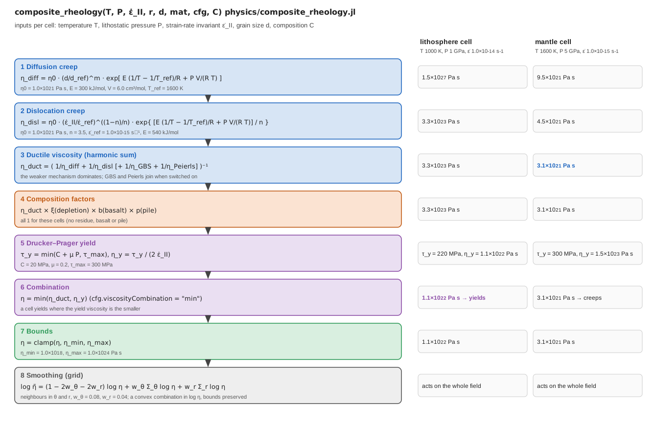
The computation for one cell, stage by stage, with the default material parameters. Right: the value each stage produces for a cold lithosphere cell (1000 K, 1 GPa, composite_rheology returns for those cells. Script: docs/scripts/fig_rheology_pipeline.jl.
1. Ductile creep
With lithostatic pressure mantle_pressure (the reference state of the selected compressibility mode) and
Here
| symbol | meaning | unit |
|---|---|---|
| absolute temperature of the cell, floored at 300 K | K | |
lithostatic pressure at the cell's depth below mat.R_surf | Pa | |
gas constant, cfg.R_GAS = 8.314 | J mol⁻¹ K⁻¹ | |
| activation energy and activation volume of the mechanism | J mol⁻¹, m³ mol⁻¹ | |
| reference viscosity of the mechanism | Pa s | |
| reference temperature at which | K | |
| grain size, reference grain size and grain-size exponent | m, m, - | |
| strain-rate invariant, reference strain rate and stress exponent | s⁻¹, s⁻¹, - | |
| grain-boundary-sliding and Peierls viscosities, infinite unless switched on | Pa s |
Where the exponents come from. These are laboratory creep laws written in a reference-viscosity form. A power law
so a stress exponent
| parameter | field | default |
|---|---|---|
mat.diff_eta0, mat.disl_eta0 | ||
mat.T_ref | 1600 K | |
diff_E_upper/lower, diff_V_upper/lower | 300 / 200 kJ mol | |
disl_E_upper/lower, disl_V_upper/lower | 540 / 300 kJ mol | |
mat.disl_n, mat.disl_eII_ref | 3.5, | |
mat.diff_m, mat.diff_d_ref | 3, 1 mm |
The lower-mantle values of cfg.useLayeredActivationEnergy = true; otherwise the upper values apply everywhere. The grain-size factor is 1 unless cfg.evolveGrainSize is on (Grain-size evolution).
Two optional mechanisms join the harmonic sum: grain-boundary sliding (cfg.useGBS, parameters cfg.gbs_A, gbs_n, gbs_m and mat.gbs_E_upper/lower) and Peierls low-temperature plasticity (cfg.usePeierlsCreep, active only where mat.flowlaw_peierls, Mei et al. 2010 by default). Both default off.
Published flow laws
Instead of the reference-viscosity laws above, the diffusion and dislocation creep of the mantle, a crustal law where there is basalt, and the Peierls law can be taken from published laboratory experiments (Hirth & Kohlstedt 2003, Karato & Wu 1993, Mackwell et al. 1998, Rybacki & Dresen 2000 and others), by name. See Flow laws.
Lower-mantle offset. With cfg.use660kmJump = true, every creep law below cfg.depth660km is multiplied by a prefactor (lower_mantle_creep_prefactors) that divides out the jump the lower_mantle_interface_TP) and multiplies by cfg.eta660kmFactor. The viscosity ratio across the interface is then exactly eta660kmFactor at the interface conditions, and the cfg.depth660km rather than mat.R_lower.
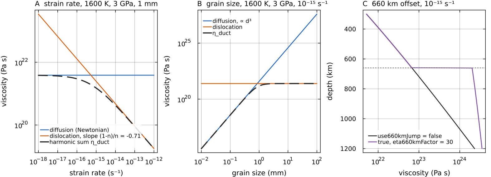
The ductile branch of composite_rheology with default parameters, yield off and clamps lifted. Left: diffusion creep is independent of the strain rate and dislocation creep falls with slope cfg.evolveGrainSize = true), and the sum saturates at the dislocation value for large grains. Right: the geotherm between 300 and 1200 km with cfg.use660kmJump and cfg.useLayeredActivationEnergy on; the viscosity rises by exactly eta660kmFactor = 30 across the interface (30.3 between the two rows that straddle it). Script: docs/scripts/fig_rheology_sections.jl.
2. Composition factors
Applied to
with mat.harzburgite_eta_factor (3), mat.basalt_eta_factor (0.1) and mat.tcpile_eta_factor (1). cfg.depletionStiffensYield = true the depletion factor also multiplies the yield viscosity.
The three factors stand for three materials whose creep strength differs from that of fertile peridotite. Melt extraction removes water and the most fusible components, and the dry, depleted residue (harzburgite) is expected to be stiffer (Hirth & Kohlstedt 1996); mat.flowlaw_crust_diffusion or mat.flowlaw_crust_dislocation), it replaces the basalt factor
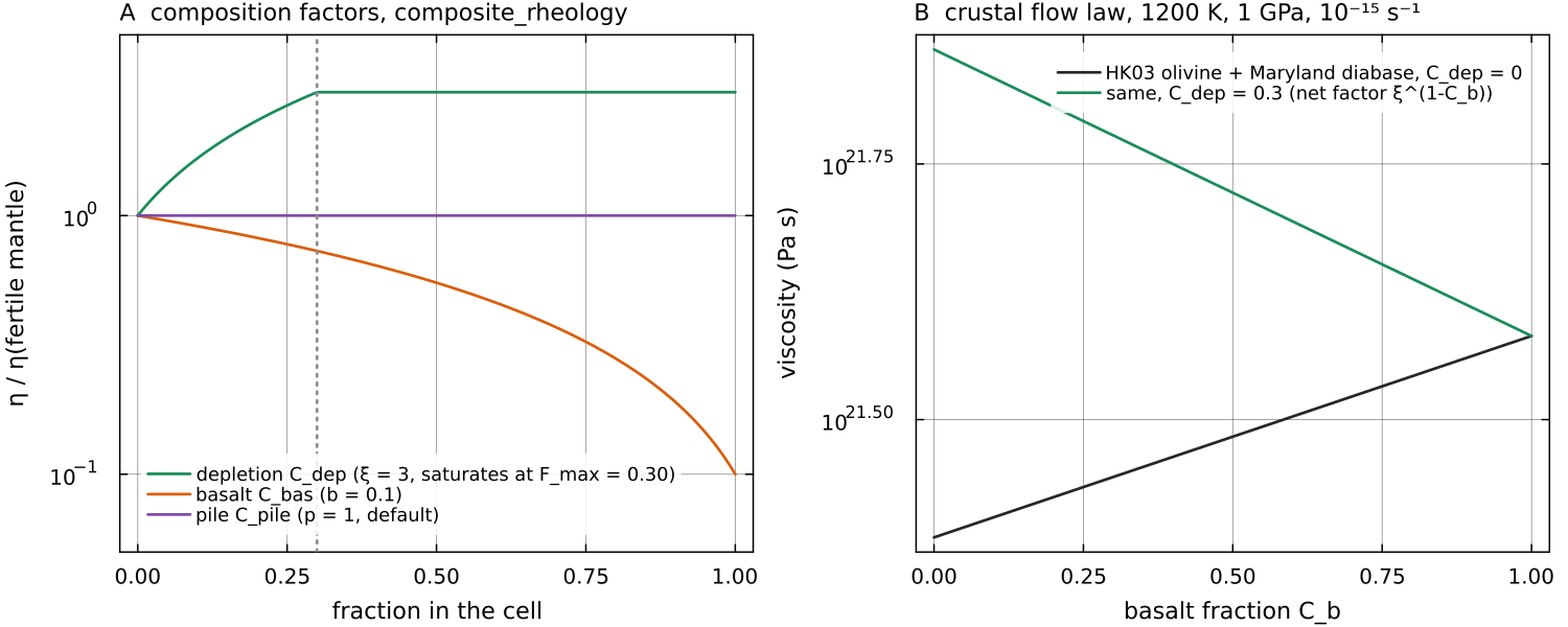
Left: the factor composite_rheology applies to the ductile viscosity of a mantle cell (1600 K, 3 GPa, docs/scripts/fig_rheology_sections.jl.
3. Drucker-Prager yield
with cohesion mat.cohesion_upper/lower (20 / 60 MPa), friction coefficient mat.friction_upper/lower (0.2 / 0.3) and cap mat.maxYieldStress (300 MPa). Where cfg.yieldMinT (default 0, i.e. nowhere) the yield branch is switched off (Inf removes yielding altogether.
Continent material can carry its own law: when mat.continent_cohesion or mat.continent_friction is set (both default to NaN, which keeps the layer's values), the cohesion and friction of a cell are mixed linearly in its continent fraction
so the yield stress is the volume-fraction average of the two, the same rule the continent viscosity factor follows.
The yield viscosity
With cfg.useFullPlasticity = true the cohesion weakens with the accumulated plastic strain
with cfg.strainWeakeningFactor (default 1, no weakening) and cfg.strainWeakeningE1/E2 (0.5, 1.5). The driver adds eps_acc every step when the flag is on (see Damage, softening and healing).
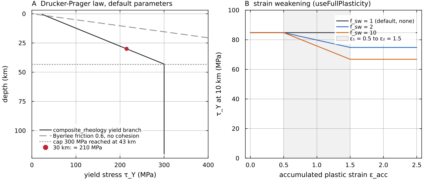
Left: the yield stress of composite_rheology's Drucker-Prager branch (mantle_pressure. It grows by about 6.5 MPa per km, reaches 210 MPa at 30 km and the 300 MPa cap at 43 km; Byerlee's friction of 0.6 without cohesion is shown for comparison. Right: with cfg.useFullPlasticity = true the cohesion weakens between cfg.strainWeakeningFactor; at 10 km only the 20 MPa cohesion is reduced, the pressure term is not. Script: docs/scripts/fig_rheology_sections.jl.
4. Combination, clamp and smoothing
cfg.viscosityCombination selects "min", default, the form of Tian et al. 2023 Eq. 6) or the harmonic mean "harmonic"). The result is clamped to
with _smooth_viscosity). Being a convex combination in log space, it preserves the clamp bounds.
The "min" rule is the strength-envelope picture of Kohlstedt, Evans & Mackwell (1995). A cell deforms by whichever mode, creep or yielding, needs the lower stress at its strain rate, and the switch between the two is sharp. The harmonic mean treats the two branches as acting in parallel; it gives a smooth transition and, where the branches are equal, a viscosity half that of the "min" rule.
The bounds and the smoothing are numerical measures rather than physics. The clamp limits the viscosity contrast the Stokes solver has to handle; a cold lid in nature can be many more orders of magnitude stiffer than
The yield law is nonlinear
The yield viscosity cfg.picardMax at its automatic value or larger for any run with a finite yield stress. Inside the sweeps composite_rheology and the damage factor are reapplied; the visco-elasto-plastic reduction and the antisqueeze correction act on the first sweep.
cfg.useDruckerPrager and the dp_* fields belong to a separate helper, utils/drucker_prager.jl, used outside the time loop; validate!(cfg) refuses useDruckerPrager = true and points to the material fields above.
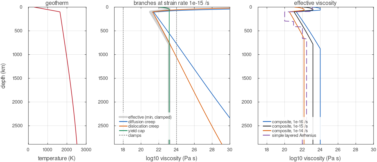
Viscosity along a geotherm (the code's adiabat at 1600 K potential temperature below a 100 km conductive lid), from composite_rheology with default parameters. Middle: each branch alone and the effective viscosity, the minimum of the branches inside the clamps; below about 700 km the default 300 MPa yield cap sets the value at this strain rate. Right: the effective viscosity at three strain rates, and the simple layered Arrhenius law of compute_viscosity on the same temperatures.
Optional modifiers
| flag | file, function | what it does | details |
|---|---|---|---|
cfg.useViscoelastoplastic | physics/viscoelastoplastic.jl, viscoelastoplastic | Maxwell viscosity with a Drucker-Prager cap | Visco-elasto-plasticity |
cfg.useDamage | physics/damage.jl, evolve_damage!, apply_damage_to_viscosity! | grid damage with healing, scales the viscosity | Damage, softening and healing |
cfg.evolveGrainSize | physics/evolve_grain_size.jl, evolve_grain_size! | wattmeter grain size on markers, feeds diffusion creep and GBS | Grain-size evolution |
cfg.useAntisqueeze | physics/antisqueeze.jl, antisqueeze | reduces | applied to the strain rate before the viscosity is built; affects only strain-rate-dependent laws |
Assumptions and simplifications
The viscosity laws above rest on choices that are standard in mantle-convection modelling. They are listed here so that a result can be read with them in mind.
One isotropic viscosity per cell. Deforming olivine develops a crystal preferred orientation and an anisotropic viscosity (Karato 2008); MILEVA represents each cell by a single scalar
. Viscous and plastic, not elastic, by default. Since the Maxwell time of the interior is centuries, elastic stresses are left out unless the visco-elasto-plastic modifier is on.
Lithostatic pressure. The creep and yield laws use the reference-state pressure of
mantle_pressureat the cell's depth; the dynamic pressure from the Stokes solution is not added.One strain rate for all mechanisms. The strain-rate-dependent laws are all evaluated at the cell's total
. For Newtonian laws this is exact. A stress-dependent mechanism that carries only part of the deformation would, in a combination at common stress, be evaluated at its own smaller strain rate and so be stiffer; the composite viscosity is therefore slightly lower than that of an exact common-stress combination where creep mechanisms share the deformation. Lagged inputs. Composition fields and the strain rate come from the previous step or the previous nonlinear sweep; on the composite path the nonlinear iteration brings viscosity and strain rate into agreement within the step.
Fixed grain size and water content. The grain size is
(or mat.flowlaw_grain_size, 1 mm, for the published flow laws) unless grain-size evolution is on, and the water measure of the published flow laws is one constant (mat.flowlaw_water), not a field.No melt weakening. The viscosity does not depend on the local melt fraction.
Simple mixing of compositions. The composition factors are linear in the material fractions.
Numerical bounds and smoothing.
, and the log-space smoothing are there for the solver, not for the physics.
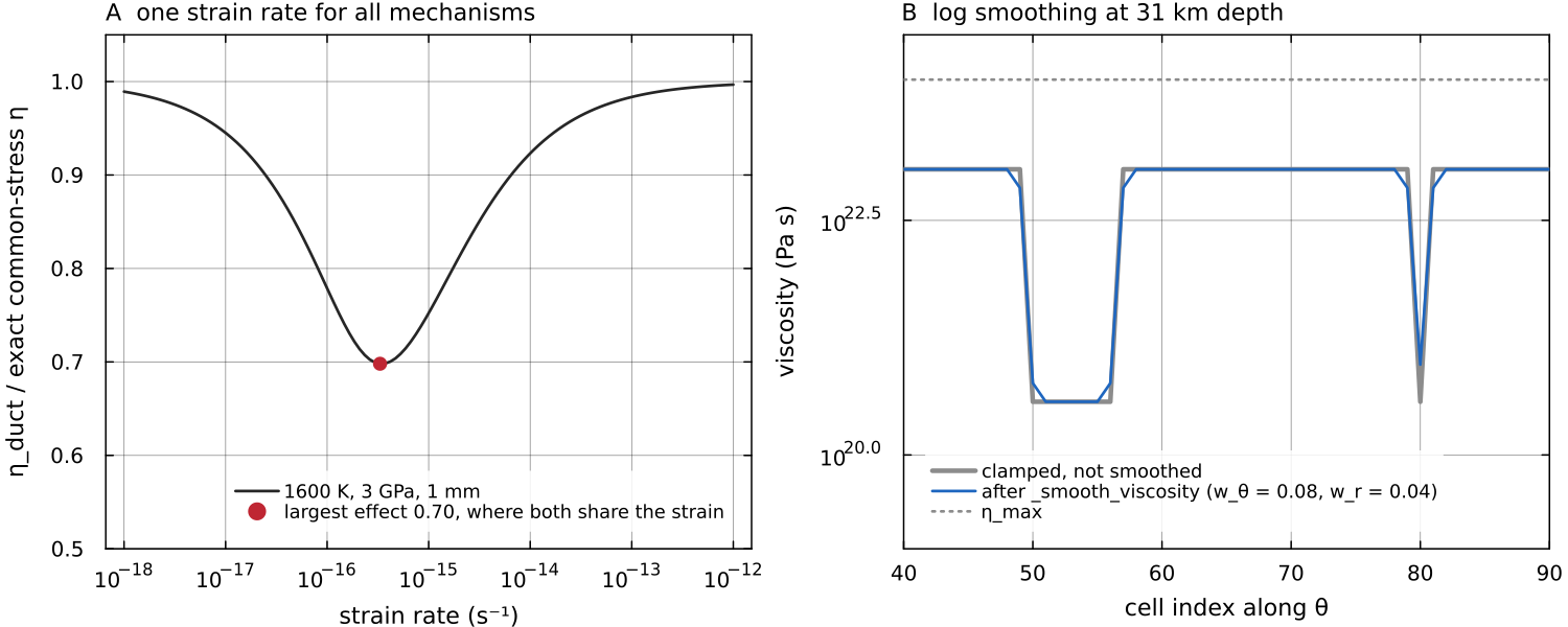
Two of the simplifications measured on the code. Left: the ductile viscosity of composite_rheology (default laws, 1600 K, 3 GPa, 1 mm) divided by the viscosity of an exact parallel combination in which the two mechanisms share one stress and their strain rates add, solved here by bisection. The two agree where one law dominates and differ by up to a factor 0.70 where they share the strain equally. Right: one row at about 30 km depth of a 40 × 120 field in which a band of cells and one isolated cell deform at _smooth_viscosity. The smoothing widens and rounds the weak zones without leaving the clamp bounds. Script: docs/scripts/fig_rheology_sections.jl.
Configuration summary
| field | default | meaning |
|---|---|---|
cfg.useCompositeRheology | false | composite path instead of layered Arrhenius |
cfg.eta_min, cfg.eta_max | global clamps | |
mat.E_act_scale, mat.V_act_scale, mat.T_ref | 200 K, 0, 1600 K | simple-path Arrhenius |
cfg.useFrankKamenetskii, cfg.fkForm | false, "linearized" | FK law on the simple path |
cfg.useDepletionStiffening | false | depletion factor on the simple path |
cfg.useSimpleYield | false | yield cap on the simple path (exercised in 2-D only) |
mat.harzburgite_eta_factor | 3.0 | |
cfg.viscosityCombination | "min" | ductile and yield combination |
cfg.continentViscosityAveraging | "factor" | continent mixing; "harmonic" averages separately bounded mantle and continent viscosities by the continent fraction |
cfg.yieldPressure | "lithostatic" | yield-law pressure; "total" adds the solved Stokes pressure |
cfg.smoothViscosity, cfg.smoothStrainRate | true, true | smoothing of the viscosity and of the strain rate the rheology reads |
cfg.initialStrainRate | 0.0 | strain rate of the first viscosity of a fresh run |
cfg.yieldMinT | 0 K | no yielding below this temperature |
cfg.useFullPlasticity | false | strain weakening of the cohesion |
cfg.use660kmJump, cfg.eta660kmFactor, cfg.depth660km | false, 30, 660 km | lower-mantle offset (composite path) |
cfg.useLayeredActivationEnergy | false | separate lower-mantle |
Tests
tests/test_composite_rheology.jl: the composite law against the formulas it documents and the physics each creep mechanism must obey.tests/test_rheology_switches.jl: the depletion factor, the yield temperature gate, the min / harmonic combination, the lower-mantle offset (horizontally averaged ratio equal to eta660kmFactorto a tolerance of 0.05) anddepletionStiffensYield, checked oncomposite_rheology(...; smooth = false).tests/test_fk_viscosity.jl,tests/test_arrhenius_viscosity.jl: the helper laws.tests/test_depletion_projection.jl: depletion reaches the viscosity and the buoyancy when melting is off.
Key references
Tian, J., Tackley, P. J. & Lourenço, D. L. (2023). The tectonics and volcanism of Venus: new modes facilitated by realistic crustal rheology and intrusive magmatism. Icarus 399, 115539.
Austin, N. J. & Evans, B. (2007). Paleowattmeters: a scaling relation for dynamically recrystallized grain size. Geology 35, 343-346.
Further reading
Schubert, G., Turcotte, D. L. & Olson, P. (2001). Mantle Convection in the Earth and Planets. Cambridge University Press. doi:10.1017/CBO9780511612879
Turcotte, D. L. & Schubert, G. (2014). Geodynamics, 3rd ed. Cambridge University Press. doi:10.1017/CBO9780511843877
Karato, S. (2008). Deformation of Earth Materials: An Introduction to the Rheology of Solid Earth. Cambridge University Press. doi:10.1017/CBO9780511804892
Ranalli, G. (1995). Rheology of the Earth, 2nd ed. Chapman & Hall.
Gerya, T. (2019). Introduction to Numerical Geodynamic Modelling, 2nd ed. Cambridge University Press. doi:10.1017/9781316534243
Karato, S. & Wu, P. (1993). Rheology of the upper mantle: a synthesis. Science 260, 771-778. doi:10.1126/science.260.5109.771
Hirth, G. & Kohlstedt, D. L. (1996). Water in the oceanic upper mantle: implications for rheology, melt extraction and the evolution of the lithosphere. EPSL 144, 93-108. doi:10.1016/0012-821X(96)00154-9
Hirth, G. & Kohlstedt, D. L. (2003). Rheology of the upper mantle and the mantle wedge: a view from the experimentalists. In Inside the Subduction Factory, AGU Geophysical Monograph 138, 83-105. doi:10.1029/138GM06
Byerlee, J. (1978). Friction of rocks. Pure and Applied Geophysics 116, 615-626. doi:10.1007/BF00876528
Kohlstedt, D. L., Evans, B. & Mackwell, S. J. (1995). Strength of the lithosphere: constraints imposed by laboratory experiments. JGR Solid Earth 100, 17587-17602. doi:10.1029/95JB01460
Mackwell, S. J., Zimmerman, M. E. & Kohlstedt, D. L. (1998). High-temperature deformation of dry diabase with application to tectonics on Venus. JGR Solid Earth 103, 975-984. doi:10.1029/97JB02671
Christensen, U. (1984). Convection with pressure- and temperature-dependent non-Newtonian rheology. Geophys. J. R. Astron. Soc. 77, 343-384. doi:10.1111/j.1365-246X.1984.tb01939.x
Solomatov, V. S. (1995). Scaling of temperature- and stress-dependent viscosity convection. Physics of Fluids 7, 266-274. doi:10.1063/1.868624
Solomatov, V. S. & Moresi, L.-N. (1996). Stagnant lid convection on Venus. JGR Planets 101, 4737-4753. doi:10.1029/95JE03361
Moresi, L. & Solomatov, V. (1998). Mantle convection with a brittle lithosphere: thoughts on the global tectonic styles of the Earth and Venus. Geophys. J. Int. 133, 669-682. doi:10.1046/j.1365-246X.1998.00521.x
Tackley, P. J. (2000). Self-consistent generation of tectonic plates in time-dependent, three-dimensional mantle convection simulations, 1. Pseudoplastic yielding. G³ 1, 2000GC000036. doi:10.1029/2000GC000036
Mitrovica, J. X. & Forte, A. M. (2004). A new inference of mantle viscosity based upon joint inversion of convection and glacial isostatic adjustment data. EPSL 225, 177-189. doi:10.1016/j.epsl.2004.06.005
Dziewonski, A. M. & Anderson, D. L. (1981). Preliminary reference Earth model. PEPI 25, 297-356. doi:10.1016/0031-9201(81)90046-7