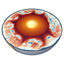
Yin-Yang grid (3-D)
MILEVA's 3-D spherical shell uses the Yin-Yang overset grid of Kageyama & Sato (2004), with the coupled Stokes solve described by Tackley (2008). Two identical latitude-longitude patches, each covering a low-latitude band, are rotated against each other so that together they cover the sphere without poles. The grid is built by _setup_grid_3d in utils/setup_grid.jl; patch-to-patch interpolation lives in utils/yy_interp.jl; the coupled Stokes solve is the 3-D method of multigrid_stokes in solvers/multigrid_stokes.jl.
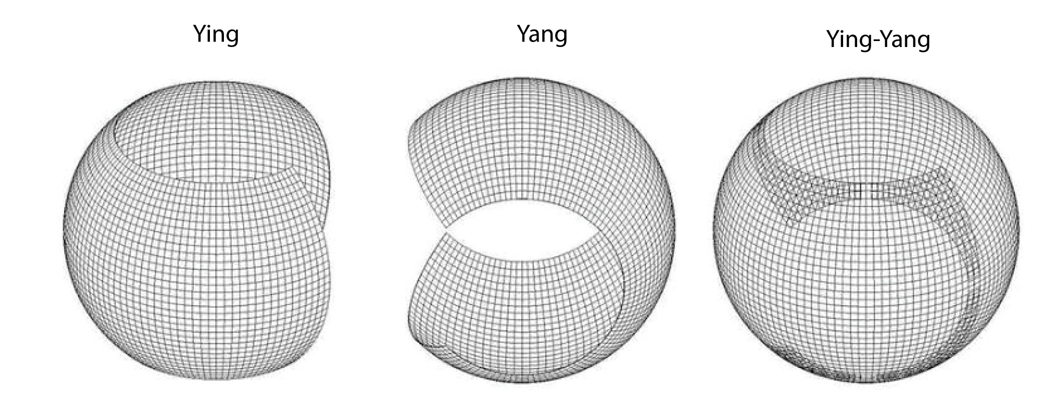
The Yin patch (left), the Yang patch (centre) and the two together (right). Both patches are the same low-latitude rectangle in their own spherical coordinates,
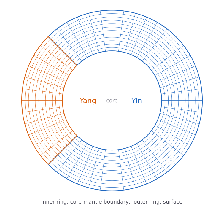
The shell in its equatorial plane. Each patch is extruded radially into docs/scripts/render_yinyang_cut.jl.
One patch
Each patch is a rectangle in its own spherical coordinates:
90° of colatitude and 270° of longitude. cfg.Nt sets cfg.chunkPhiRange below
The grid stores one patch geometry (MutableGrid3D); the Yang patch has the same parametric grid, and its fields are held separately by the solvers.
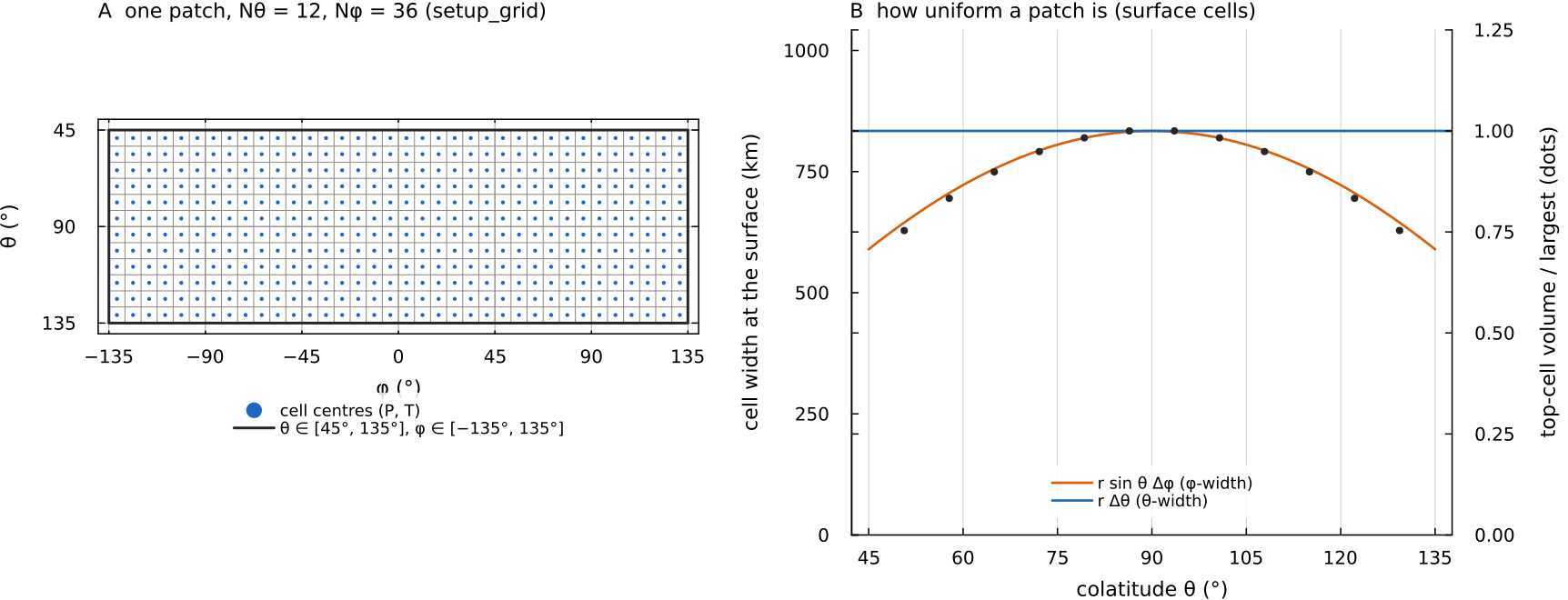
Left: the parametric grid that setup_grid builds for cell_volumes (dots) to 0.75 of the largest. A latitude-longitude grid restricted to low latitudes stays this close to uniform, which is the point of the construction. Script: docs/scripts/fig_numerics_yin_yang_sections.jl.
The Kageyama-Sato transform
Yang's Cartesian frame is Yin's frame under the rotation
which satisfies yy_yin_to_yang and yy_yang_to_yin in utils/setup_grid.jl implement it on
Scalars (
returned as yy_rotation_yin_to_yang and yy_rotation_yang_to_yin. This is Kageyama & Sato's vector rotation (their Eqs. 22 to 24) with the opposite sign convention for the angle, used consistently in both directions; tests/test_yy_rotation_vs_ks2004.jl checks it against the paper to machine precision (
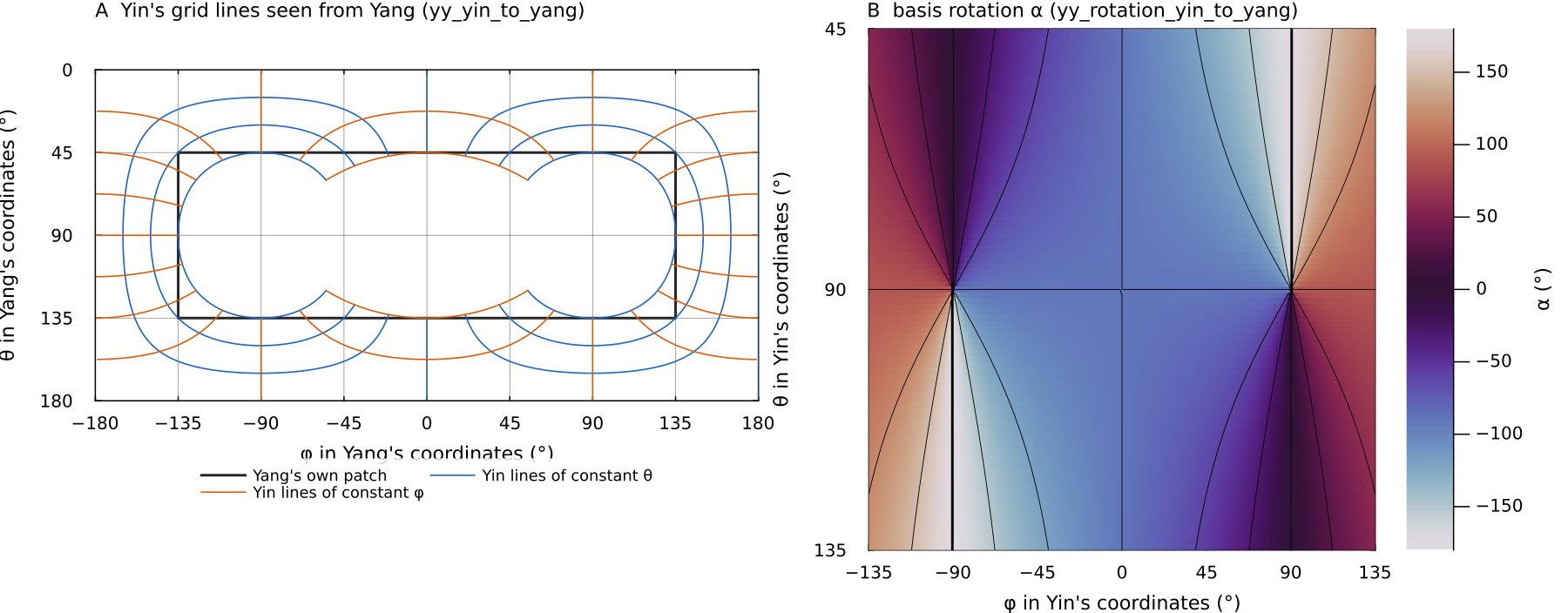
Left: lines of constant yy_yin_to_yang. Yin covers everything outside the white "baseball" region; inside Yang's own rectangle (black), the band between that region and the rectangle is the overlap that both patches hold. Right: the angle yy_rotation_yin_to_yang. It winds through 360° around the two points at docs/scripts/fig_numerics_yin_yang_sections.jl.
Coupling the patches: Schwarz iteration
The two patches are solved separately and coupled by an overlapping Schwarz iteration on their walls. In the 3-D multigrid_stokes, each of n_schwarz rounds (default 5, fixed, no tolerance test) does:
yy_compute_th_bcs(:yin_dest, ...; full = true)samples Yang's current velocity at the positions that Yin's-walls need and rotates the tangent components into Yin's basis. This gives Dirichlet values for on the wall faces and ghost values for and next to them. The right-hand side of Yin's system is re-assembled with those values (
assemble_stokes_3d(...; rhs_only = true), since the matrix does not depend on boundary values) and Yin is solved with FGMRES and a multigrid preconditioner (see Geometric multigrid).The same is done for Yang from the new Yin solution.
The Schwarz residual (largest change in any velocity component over info.schwarz_residuals. The Yin solution is returned as the primary field and Yang's in info.yang.
Interpolation is bilinear in _bilinear_sample_3d). A Catmull-Rom bicubic sampler (_bicubic_sample_3d) is available behind _USE_BICUBIC_YY[]; bilinear is the default.
Which walls are coupled
On the multigrid path, the one 3-D runs use, only the yy_compute_ph_bcs) exists, and the single-level direct path calls it. The multigrid path leaves it out because on the equator Yin's cfg.δ_yy, default 0, with YYBufferTheta and YYBufferPhi in utils/yy_buffer.jl) is available and off by default.
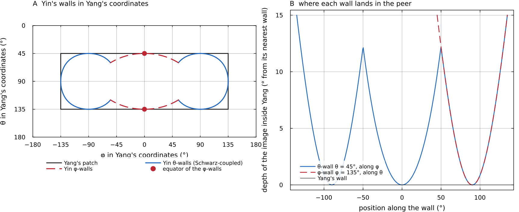
Left: Yin's docs/scripts/fig_numerics_yin_yang_sections.jl.
The halo shift
Sampling the peer at the geometric ghost position does not converge: near the corners of the overlap that position maps onto, or next to, the peer's own wall, and the two walls feed back on each other. yy_compute_th_bcs therefore samples the peer a fixed angular distance past the destination wall,
that is, 30° of arc at any resolution (4 cells at
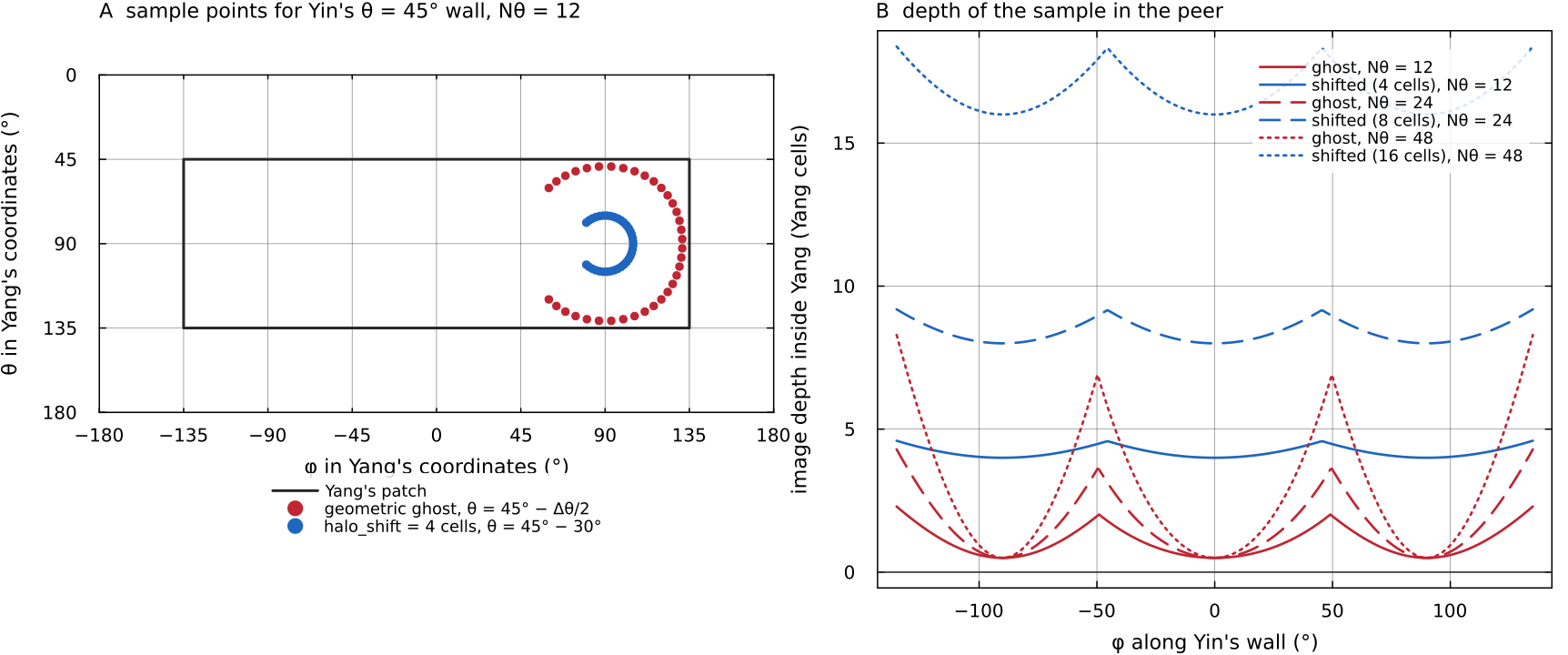
Left: in Yang's coordinates, where Yin's yy_compute_th_bcs samples it, 30° past the wall (blue). Right: the depth of each sample inside Yang, in Yang cells, along the wall for docs/scripts/fig_numerics_yin_yang_sections.jl.
Seam
The shifted sample stands in for the wall value, so velocities differ slightly between the patches along the seam, more for broad flow than for localised plumes. Quantities measured across the seam are best read from refined grids.
The temperature uses the same idea with fewer steps. In the time loop, yy_compute_T_wall_bcs samples the peer temperature at each patch's cfg.nTSchwarz times per step (default 3), and yy_sync_T_walls! then overwrites each patch's wall-cell row with the peer value at that cell centre.
Minimum overlap
The basic Yin-Yang grid overlaps by about 6 % of the sphere. Tackley (2008, §3.1) describes a minimum-overlap grid instead, whose patch boundary follows a "baseball" curve: the corner cells that lie entirely inside the other patch are removed, so wall samples fall in the peer's interior by construction.
MILEVA offers this as an option on its rectangular patch arrays (cfg.useMinOverlapGrid, default false):
_setup_grid_3dmarks a cell as redundant when all four of its corners map into the peer's domain (live_mask, about 4.6 % of cells at= 12, all at the patch corners), and builds a compact live-cell index ( compact_idx,live_cells).Redundant velocity DOFs take peer-sampled values (
yy_compute_redundant_values), and their matrix columns are eliminated from the live rows so they enter as known values on the right-hand side.FGMRES runs on the live submatrix, with a V-cycle that also operates on the compact system.
Markers in redundant cells are handed to the peer, and redundant-cell temperatures are taken from the peer (
yy_sync_T_redundant!).
FGMRES iterations to
| Contrast | Minimum overlap off | Minimum overlap on |
|---|---|---|
| 40 | residual | |
| 30 | residual | |
| 13 | 15 | |
| 15 | 19 | |
| 14 | 15 |
The option narrows the seam (on an axisymmetric
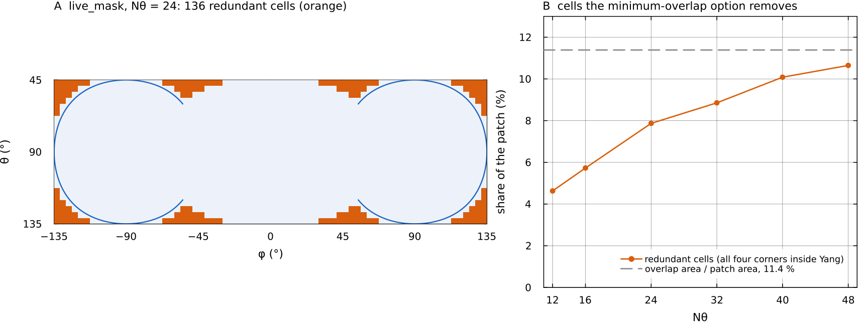
Left: the live_mask that setup_grid builds with useMinOverlapGrid = true at docs/scripts/fig_numerics_yin_yang_sections.jl.
Where in the code
| Topic | File | Function |
|---|---|---|
| Patch grid, minimum-overlap mask | utils/setup_grid.jl | _setup_grid_3d, yy_yin_to_yang, yy_yang_to_yin |
| Vector rotation, samplers | utils/yy_interp.jl | yy_rotation_yin_to_yang, _bilinear_sample_3d, _bicubic_sample_3d |
| Stokes wall values | utils/yy_interp.jl | yy_compute_th_bcs, yy_compute_ph_bcs, yy_compute_redundant_values |
| Temperature coupling | utils/yy_interp.jl | yy_compute_T_wall_bcs, yy_sync_T_walls!, yy_sync_T_redundant!, yy_init_scalar_yang |
utils/yy_buffer.jl | YYBufferTheta, YYBufferPhi | |
| Schwarz Stokes | solvers/multigrid_stokes.jl | multigrid_stokes(::MutableGrid3D, ...) |
| Two-rank MPI Schwarz | solvers/multigrid_stokes_mpi.jl, parallel/yinyang_mpi.jl | multigrid_stokes_mpi!, yy_sync_T_walls_mpi! |
| Tests | tests/ | test_yy_rotation_vs_ks2004.jl, test_yinyang_phi_coupling_ab.jl, smoke_stokes_3d_mg.jl |