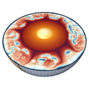
Governing equations
MILEVA solves infinite-Prandtl-number thermal and thermochemical convection in a planetary mantle: a Stokes problem for velocity and pressure at every time step, coupled to an energy equation for temperature and to a marker description of composition. All fields are carried in SI units. The Stokes assembly rescales them internally before the linear solve (see Nondimensionalisation and the Rayleigh number).
This page covers the conservation equations, the two domains the code runs in, the mechanical boundary conditions and the compressibility options. The material laws and source terms that close the system have their own pages: Rheology, Buoyancy and composition, Melting and crust production, Heat sources and thermal boundaries and Free surface and isostasy.
Physical background
Why a solid mantle convects
The rock of a planetary mantle is solid on the time scale of seismic waves, yet over millions of years it creeps. At mantle temperatures, crystals deform by the slow motion of vacancies and dislocations, and a rock volume under a sustained stress strains at a rate proportional to some power of that stress. On geological time scales the mantle therefore behaves as a very viscous fluid, with a viscosity of order
A planet loses heat through its surface while its interior is heated from below by the core and from within by the decay of radioactive isotopes. Rock that is hotter than its surroundings is less dense by
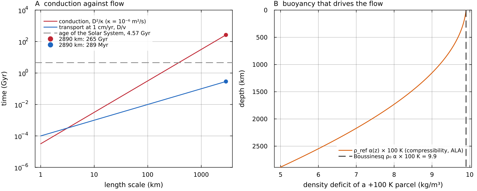
A: the conduction time compressibility under ALA, 9.9 kg/m³ at the surface and half that at the CMB, where the expansivity is lower. Script: docs/scripts/fig_governing_equations_sections.jl.
A fluid without inertia
Mantle flow is extremely slow and extremely viscous. Two numbers make this precise. The Prandtl number
A disturbance in the velocity field is therefore damped by viscosity almost instantly compared with any thermal process, and the flow at each instant is the one that balances the forces acting at that instant. This is the infinite-Prandtl-number limit (Jarvis & McKenzie 1980; Schubert, Turcotte & Olson 2001). The momentum equation loses its time derivative and its advective acceleration and becomes the Stokes equation, a boundary-value problem with no memory of the previous velocity. All the time dependence of mantle convection then enters through the energy equation and through composition. Temperature and composition evolve, and the velocity follows them. This is why MILEVA solves a Stokes problem at every step and advances only temperature and the markers in time.
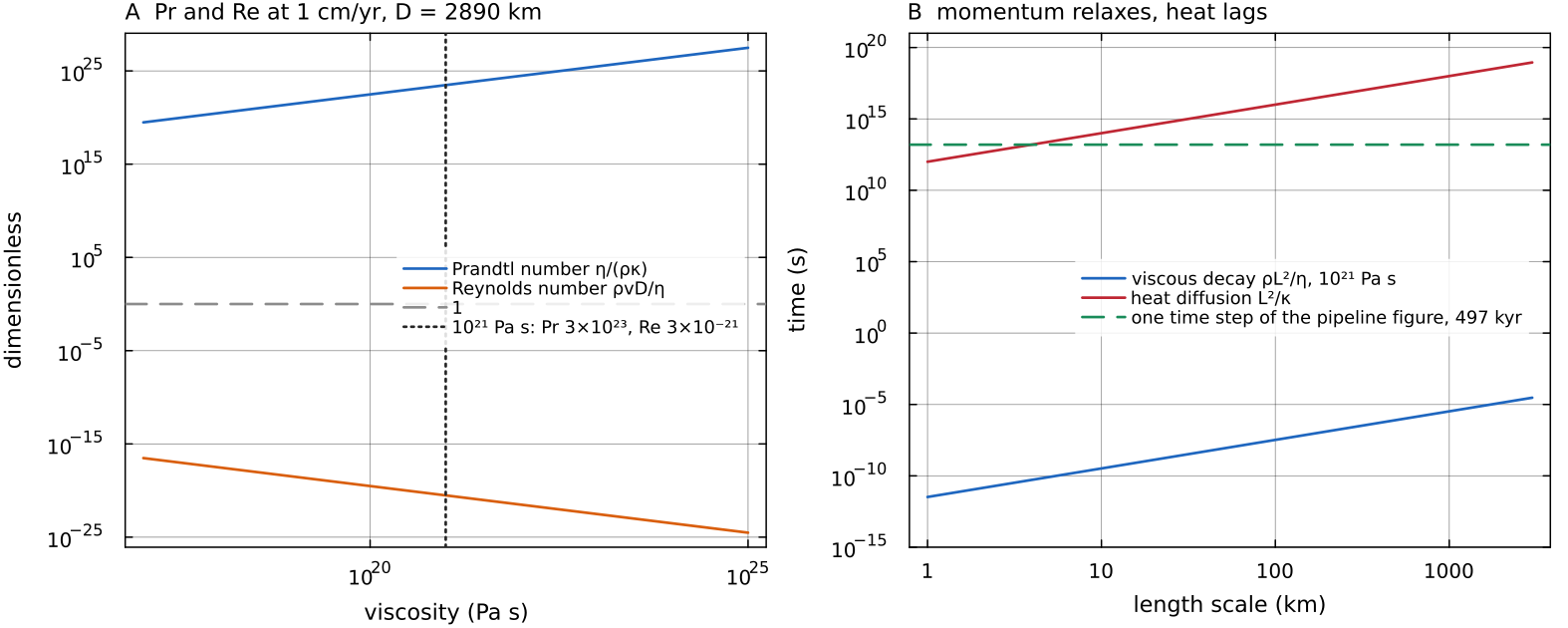
A: the Prandtl and Reynolds numbers for docs/scripts/fig_governing_equations_sections.jl.
The dimensionless numbers that organise the problem
Writing the equations in units of the layer thickness
| number | definition | what it measures |
|---|---|---|
| Rayleigh number | thermal buoyancy against viscous resistance and conduction; convection needs | |
| Péclet number | heat carried by flow against heat carried by conduction | |
| dissipation number | strength of adiabatic heating and cooling, and of viscous dissipation, relative to the other terms of the energy equation | |
| viscosity contrast | how strongly temperature, pressure and composition change the viscosity; large contrasts produce a stiff surface lid | |
| Prandtl number | taken as infinite (see above) |
Boundary-layer theory gives the leading behaviour of a vigorously convecting layer. The cold top boundary layer thickens by conduction until it becomes locally unstable, which gives a thickness of order
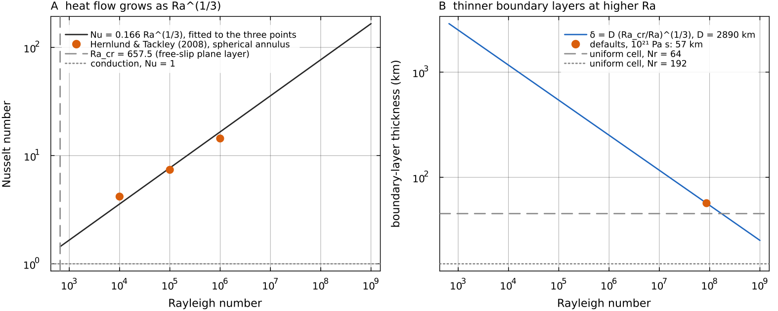
A: the scaling docs/scripts/fig_governing_equations_sections.jl.
Typical values
With MILEVA's default parameters (SimConfig: TemperatureConditions: 4000 K at the CMB and 300 K at the surface) and
| quantity | value |
|---|---|
| about | |
| about 0.7 with the surface expansivity, 0.2 with the CMB value | |
| about 900 | |
| about 60 km |
These are order-of-magnitude figures, not model outputs. The full CMB-to-surface temperature difference overstates the part that drives convection, because the adiabatic increase of temperature with depth carries no buoyancy, and the effective viscosity of a real mantle varies by many orders of magnitude.
The Earth's mantle convects at velocities comparable with plate motions, a few centimetres per year, and its surface is broken into mobile plates (Turcotte & Schubert 2014). Venus has a similar size and bulk composition but no plate tectonics today. Its surface is a single lid, interpreted as a stagnant lid or one that is renewed episodically (Solomatov & Moresi 1996; Nimmo & McKenzie 1998). Solomatov & Moresi (1996) estimate the interior viscosity beneath that lid at order
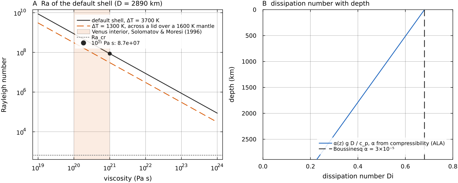
A: compressibility (ALA), 0.68 at the surface and 0.23 at the CMB, against the constant Boussinesq value. Script: docs/scripts/fig_governing_equations_sections.jl.
How one time step solves the equations
The equations are not solved all at once. Each time step goes through them in a fixed order. The temperature carried by the markers is first averaged onto the grid, and from it the code builds a viscosity and a buoyancy force. The Stokes equations then give the velocity that this force drives at this instant, because the mantle has no inertia. The velocity sets how long the step may be, the markers move with it, and finally heat is conducted, produced and consumed over that interval before the change in temperature is handed back to the markers.
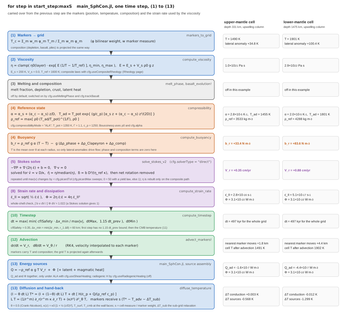
One time step of the 2-D loop in main_SphCon.jl, with its own step numbers in brackets, for the default configuration (spherical annulus, ALA, simple Arrhenius viscosity) on a 48 × 192 grid holding an adiabatic mantle with a ±100 K degree-2 temperature anomaly. The right-hand column gives the values for a cell at 331 km and a cell at 1475 km depth in the hot, upwelling column. Their anomalies of 34.8 K and 100.4 K give a buoyancy of 33.4 and 83.6 N m⁻³, an upward velocity of 0.35 and 0.88 cm/yr and a 497 kyr step, over which adiabatic cooling of the rising material lowers the temperature by 0.57 and 1.30 K while conduction changes it by less than 0.02 K. Every value is returned by the function named in its box. The script checks each against the formula shown, and the velocity and dissipation through the work-dissipation identity (1.022 over the whole shell on this grid). Script: docs/scripts/fig_governing_equations_pipeline.jl.
Momentum and mass
The momentum balance is the divergence of the full deviatoric stress against a buoyancy force
That is the Boussinesq mass balance. Under ALA and TALA the 2-D annulus solves the anelastic one instead (Jarvis & McKenzie 1980), with the pressure term and the stress written to match it:
with
Here compute_buoyancy (physics/compute_buoyancy.jl) from density anomalies relative to the reference state, so the hydrostatic part never enters the solve. The thermal, phase and pile terms are lateral anomalies (the mean at each radius removed); the depletion, eclogite and crust terms are not mean-removed, and their radial mean changes only the pressure; see Buoyancy and composition. There is no inertia term and no elastic stress memory in the momentum equation.
Each term has a direct physical reading.
| symbol | meaning | unit |
|---|---|---|
| velocity of the mantle rock | m s⁻¹ | |
| dynamic pressure, the departure from the hydrostatic (reference) pressure | Pa | |
| effective shear viscosity, supplied by the rheology | Pa s | |
| strain-rate tensor, the symmetric part of the velocity gradient | s⁻¹ | |
| deviatoric (viscous) stress; under ALA/TALA | Pa | |
| buoyancy force per unit volume, positive outward | N m⁻³ |
The equation states that, at every point, three forces per unit volume cancel. The buoyancy
- is not part of
. It is carried separately by the reference state and enters the material
laws through mantle_pressure (see Compressibility modes). The
The mass equation
The viscosity is what makes the problem hard. Through its strong dependence on temperature, pressure, stress and composition,
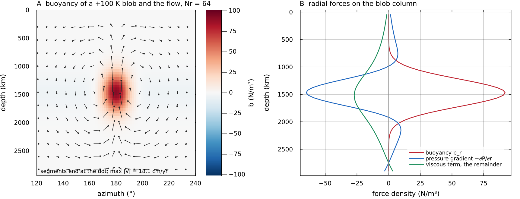
A direct solve of assemble_stokes on a Venus-sized spherical annulus (Boussinesq, docs/scripts/fig_governing_equations_sections.jl.
The 2-D operator is assembled as ∇·(2η ε̇)
assemble_stokes (solvers/stokes_assembly.jl) builds the viscous block through _viscous_block_deviatoric, which factors the operator as
and the momentum rows are
with continuity
Under ALA and TALA three things change, all in assemble_stokes. The continuity rows carry the radial MASS flux, with anelastic_density:
The radial pressure term becomes the adjoint of those rows,
so compute_strain_rate returns the deviatoric invariant and components, so the rheology, the dissipation compute_strain_rate (utils/compute_strain_rate.jl), so the rheology sees the strain rate the operator implements.
The switch is cfg.useDeviatoricStress (default true). Setting it false assembles
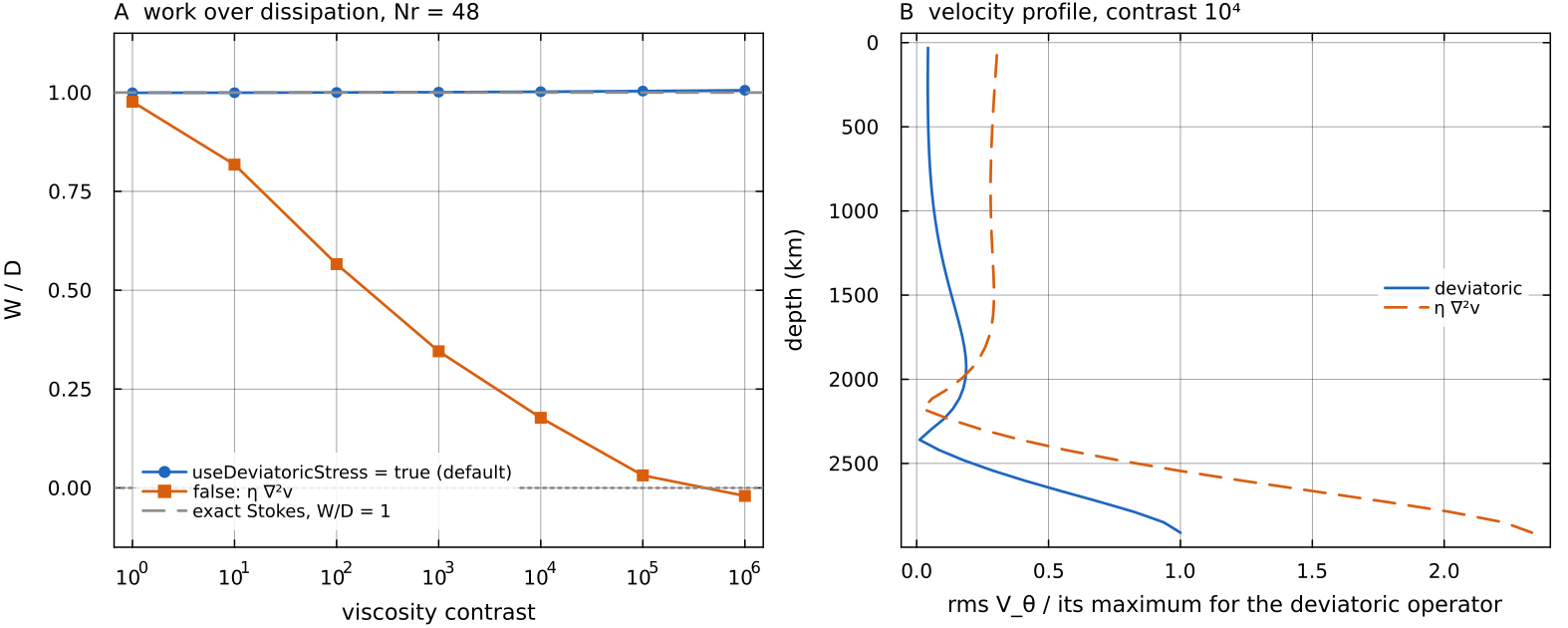
Buoyancy work over viscous dissipation for a smooth load on an exponential radial viscosity ramp, 48 × 192 cells, spherical annulus, solved with useDeviatoricStress = true and false. A: the deviatoric operator stays at docs/scripts/fig_governing_equations_sections.jl.
Staggered grid
The 2-D unknowns sit on a staggered (MAC) grid: solvers/stokes_assembly_3d.jl) uses the same staggering on each Yin-Yang patch and geometric means for face and edge viscosities by default (cfg.useGeometricEta = true).
The staggered arrangement goes back to Harlow & Welch (1965) and is the standard finite-difference discretisation of incompressible viscous flow in geodynamics (Gerya 2019). Placing each velocity component on the faces it crosses makes the discrete divergence of a cell a simple balance of the fluxes through its own faces, so mass conservation is exact cell by cell, and it couples neighbouring pressures directly, so the spurious chequerboard pressure mode that a collocated grid admits does not arise.
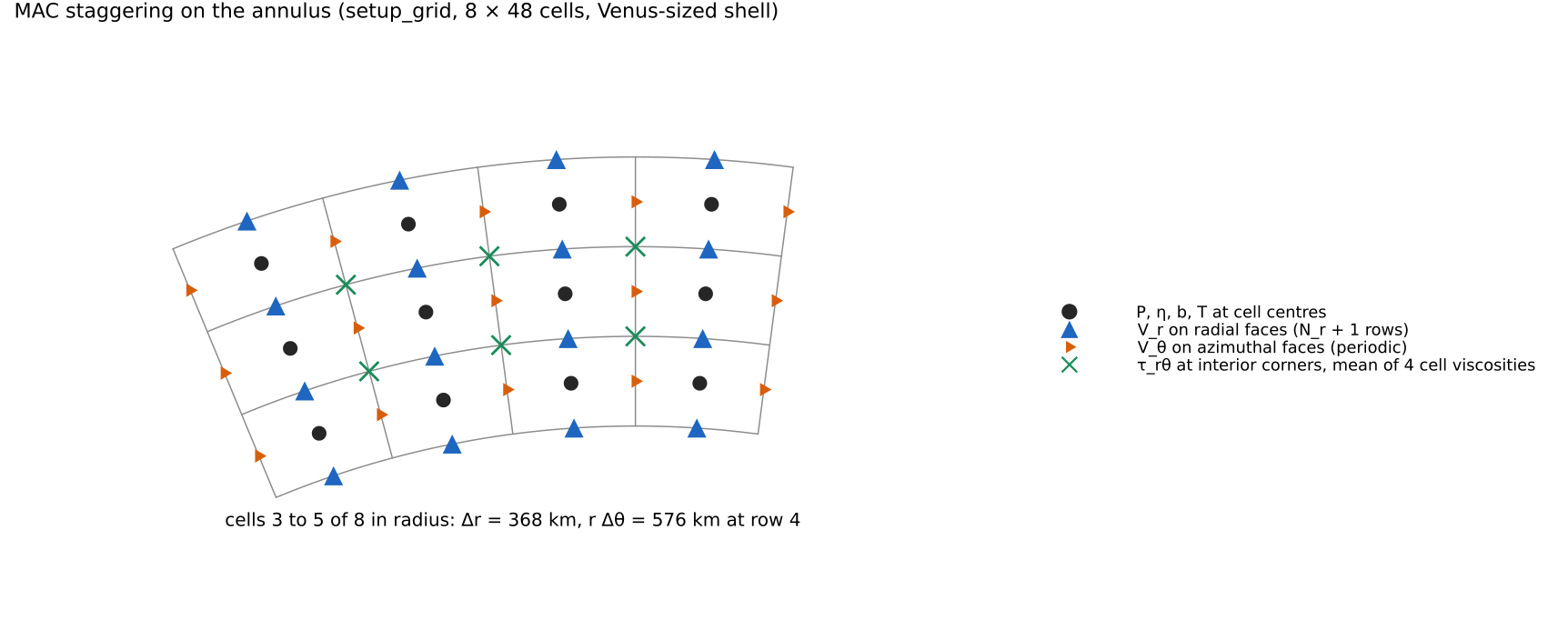
Where the 2-D unknowns live, drawn from the coordinates of setup_grid on a coarse 8 × 48 Venus-sized annulus (grid.r, grid.rF, grid.th): pressure and the cell fields at the centres, docs/scripts/fig_governing_equations_sections.jl.
Domains: the spherical annulus and the 3-D shell
MILEVA runs in two domains. The 2-D mesh is a full cfg.R_in and cfg.R_out; the 3-D mesh is a Yin-Yang spherical shell of two identical patches of
In 2-D everything that distinguishes one radially symmetric geometry from another reduces to the exponent geometry_exponent(cfg) in utils/geometry.jl. The mesh is identical; only the metric factors change.
| 2-D spherical annulus | 2-D cylindrical annulus | 3-D Yin-Yang shell | |
|---|---|---|---|
cfg.geometry / cfg.dim | "spherical_annulus", dim = 2 (default) | "cylindrical_annulus", dim = 2 | dim = 3 |
| measure | 2 | 1 | true sphere |
| cell measure | |||
| radial divergence | |||
| inner/outer area ratio (Venus, 3110/6052 km) | 0.264 | 0.514 | 0.264 |
The spherical annulus is the equatorial slice of a spherical shell with the latitude-variation terms dropped. Its boundary area ratio, volume weighting and radial divergence match the sphere, which is why it is the default and the geometry every example and benchmark in this documentation uses. The cylindrical annulus over-weights the core-mantle boundary by a factor 1.95 on a Venus-sized body; it is available for comparison with cylindrical models. validate!(cfg) refuses the bare string "annulus" because the two choices give different answers.
Helpers in utils/geometry.jl (shell_measure, cell_measure, radial_flux_weight, geometry_area_ratio) give every operator the same metric: the Stokes assembly, the conservative temperature diffusion (solvers/diffuse_temperature.jl), the strain rate, the Nusselt baseline (conductive_baseline_C in physics/compressibility.jl), the core heat capacity and CMB area (physics/cmb_heat_flux.jl) and the marker weights.
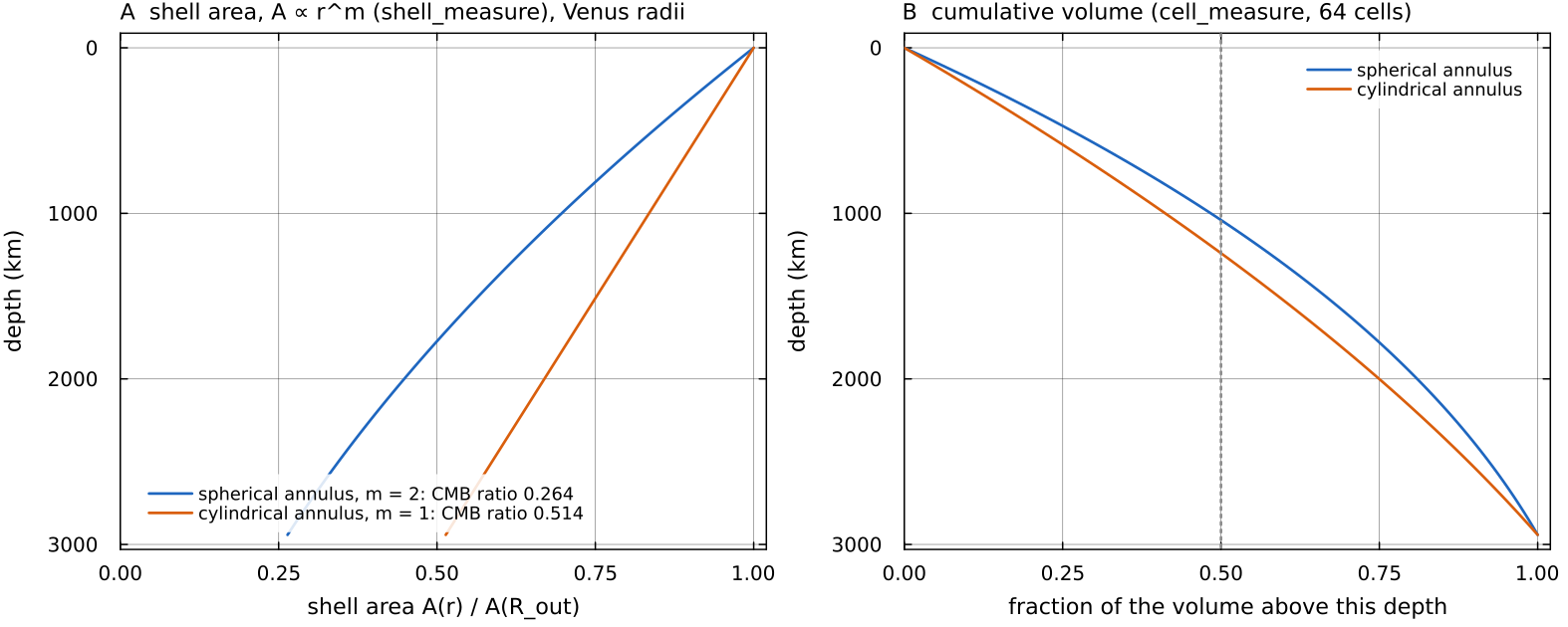
The two 2-D geometries on Venus radii (3110 to 6052 km). A: the shell area from shell_measure, with the CMB-to-surface ratios of geometry_area_ratio, 0.264 spherical and 0.514 cylindrical. B: the fraction of the volume lying above each depth, summed from cell_measure over 64 cells. Half of the spherical annulus lies above 1011 km depth, against 1195 km for the cylinder, which gives the deep mantle more weight. Script: docs/scripts/fig_governing_equations_sections.jl.
Mechanical boundary conditions and null modes
Both walls are impermeable and free slip:
| wall | condition | implementation |
|---|---|---|
| CMB | identity rows on the first and last assemble_stokes | |
| same | zero shear traction, | the wall shear flux is dropped in _viscous_block_deviatoric |
| azimuth (2-D) | periodic | jminus / jplus wrap-around |
| 3-D patch edges | Schwarz coupling to the other Yin-Yang patch | multigrid_stokes (solvers/multigrid_stokes.jl) |
The top is therefore a fixed, flat surface. Deflections of it are handled separately and approximately; see Free surface and isostasy.
The 2-D system has two null modes. The pressure constant is fixed by replacing the continuity row of one central cell with a pressure pin (a single-point pin, point_pin = true, in every 2-D solver), and solid-body rotation by pinning one cfg.removeNetRotation = true (default), the 2-D driver then removes the rigid rotation _net_rotation_rate in main_SphCon.jl), so surface velocity and lid mobility are reported in a no-net-rotation frame.
Here cell_measure), so the sums are the angular momentum and the moment of inertia in the measure validate! warns once when removeNetRotation is set for dim = 3.
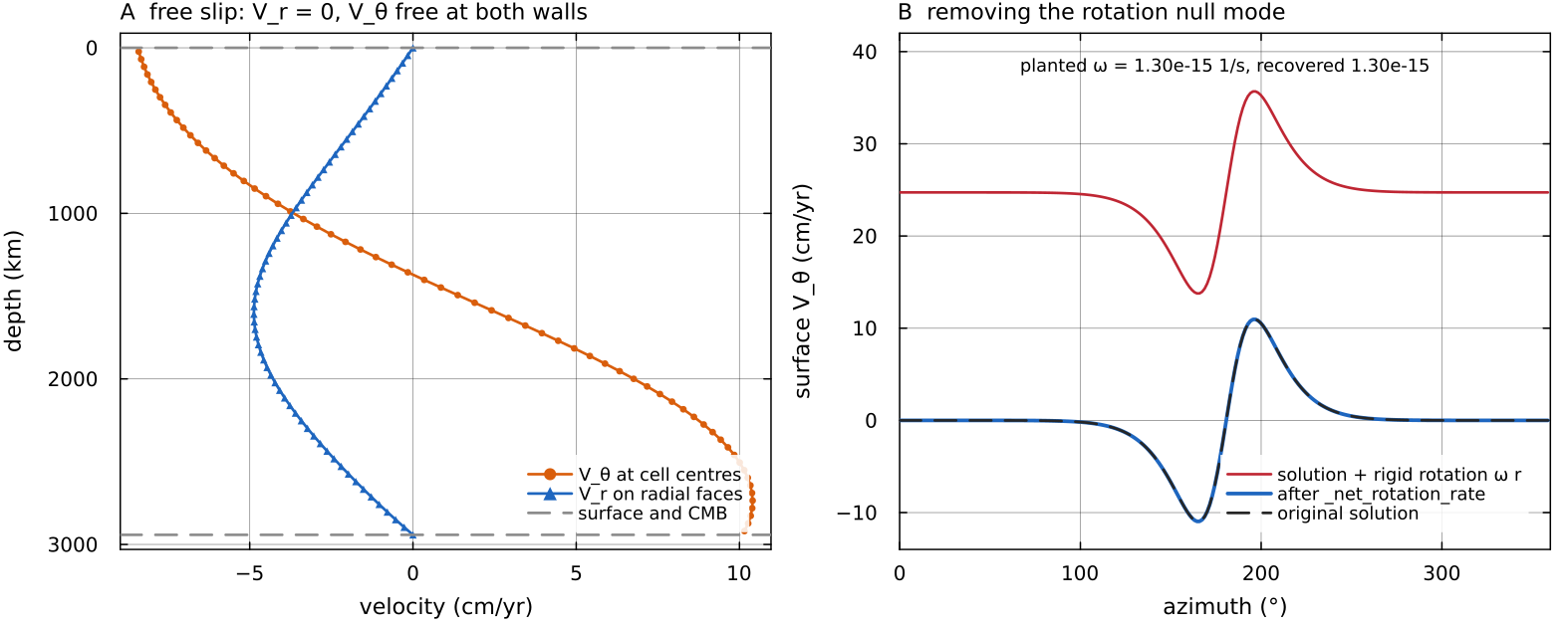
The blob solution of the momentum figure (64 × 256 cells). A: at a column 25° from the blob, _net_rotation_rate, which recovers it and returns the original surface velocity. Script: docs/scripts/fig_governing_equations_sections.jl.
Energy equation
Temperature obeys
with CP_REF in physics/compressibility.jl, Cp_avg in solvers/diffuse_temperature.jl),
The equation above is the Boussinesq form, where
so each cell divides the net conducted power through its faces by its own conduction_coefficients in physics/compressibility.jl, used by every 2-D and 3-D path of diffuse_temperature). Conduction then changes the thermal energy budget_resid of the Earth example measures.
Read from left to right, the equation is a heat budget for a parcel of rock that moves with the flow.
| term | meaning |
|---|---|
| rate of change of temperature following the moving parcel (the material derivative): local change plus heat carried in by the flow | |
| conduction terms with | Fourier conduction, the net heat diffusing into the parcel from warmer neighbours; |
| warming by heat produced inside the rock per unit mass, mainly the decay of U, Th and K | |
| warming or cooling by heat sources and sinks given per unit volume |
Dividing a power per unit mass by
Splitting the equation into an advection part and a diffusion-and-source part reflects this division of labour. Advection with markers moves temperature with little of the numerical diffusion that a low-order grid scheme adds to sharp fronts, and the diffusion step treats conduction on the grid, where the conservative flux form keeps the discrete heat budget closed.
The equation is split. In 2-D the advection is done by the markers, which carry temperature, and the diffusion and sources are solved on the grid by diffuse_temperature and handed back to the markers as an increment (cfg.temperatureOnGrid = false, default). Setting cfg.temperatureOnGrid = true advects temperature on the grid instead (advect_temperature_2d). In 3-D the Yin patch temperature is carried by the markers as in 2-D (cfg.temperatureOnGrid is ignored in 3-D, main_SphCon.jl). The Yang patch temperature is advected on the grid with the first-order advect_temperature_3d_upwind!, whatever cfg.tempAdvectionScheme says. The sources and the thermal boundary conditions are described in Heat sources and thermal boundaries.
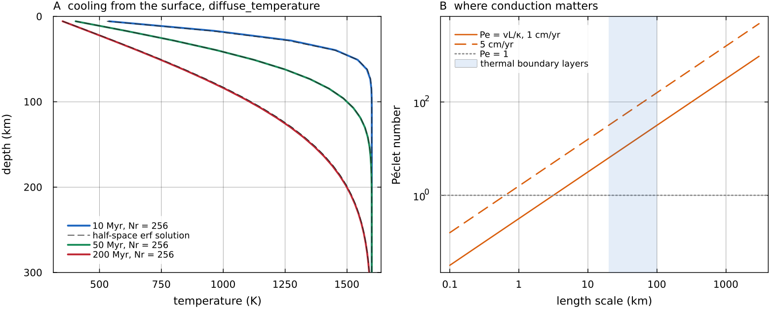
A: diffuse_temperature (Crank-Nicolson, 0.25 Myr steps, 256 radial cells, no flow and no heating) cooling a 1600 K shell from a 300 K surface, against the half-space solution docs/scripts/fig_governing_equations_sections.jl.
Compressibility modes
Rock is compressed by the weight of the rock above it. Along an adiabat, the temperature profile that a parcel follows when it moves without exchanging heat, compression raises the temperature by
Two consequences follow. A rising parcel cools adiabatically and a sinking one warms, which reduces the temperature contrast that drives the flow; and the work done by buoyancy is dissipated as heat inside the mantle rather than lost. In the anelastic liquid approximation (ALA) these effects are kept by writing every field as a time-independent, radially varying reference state, the adiabat and its density, plus the departure from it that the flow carries. MILEVA builds that reference state from a few parameters, as follows.
cfg.compressibilityMode selects the reference state, through compressibility in physics/compressibility.jl:
| mode | reference density | expansivity | diffusivity | adiabatic heating and dissipation |
|---|---|---|---|---|
"Boussinesq" | cfg.alpha | cfg.kappa | none | |
"ALA" (default) | both, if cfg.useShearHeating (default true) | |||
"TALA" | neither |
The labels follow common usage with one difference worth knowing. In King et al. (2010) the truncated anelastic liquid approximation (TALA) keeps the adiabatic heating and dissipation of ALA and instead drops the dynamic-pressure contribution to the buoyancy. MILEVA's thermal buoyancy under both ALA and TALA is compute_buoyancy are added (main_SphCon.jl, step 4). In 2-D both modes also carry the dynamic-pressure term "TALA" means the same reference state and mass balance with adiabatic heating and dissipation switched off.
Under ALA and TALA the reference state is the standard anelastic-liquid form, as in King et al. (2010). With depth
with cfg.alpha_surf_ref, cfg.alpha_cmb_ref, cfg.T_potential_ref and the Grüneisen parameter cfg.gruneisen (default 1.1), and cfg.kappaDepthFactor (default 0.5; 0 keeps adiabat_temperature, reference_density, thermal_diffusivity), with cfg.R_out and cfg.R_out cfg.R_in. reference_density is the one profile the buoyancy, the energy sources, the conductivity and the energy budget read. The lithostatic pressure used by the creep and melting laws, including the simple viscosity law compute_viscosity, is mantle_pressure (physics/melt_phase.jl), which integrates this same
The adiabatic heating term is cfg.useShearHeating, because in a statistically steady layer the volume integral of one balances the other; including only one injects or removes that whole power (main_SphCon.jl, energy source assembly).
Under ALA and TALA the 2-D mass balance is anelastic, advect_temperature_2d, advective form delivery_scale), and the net rotation is removed in the frame of zero angular momentum tests/test_anelastic_mass_balance.jl). Before, the 2-D continuity was validate! warns; cfg.useCompressibleStokes, which scaled the 3-D radial fluxes by an invented ramp thermal_diffusivity).
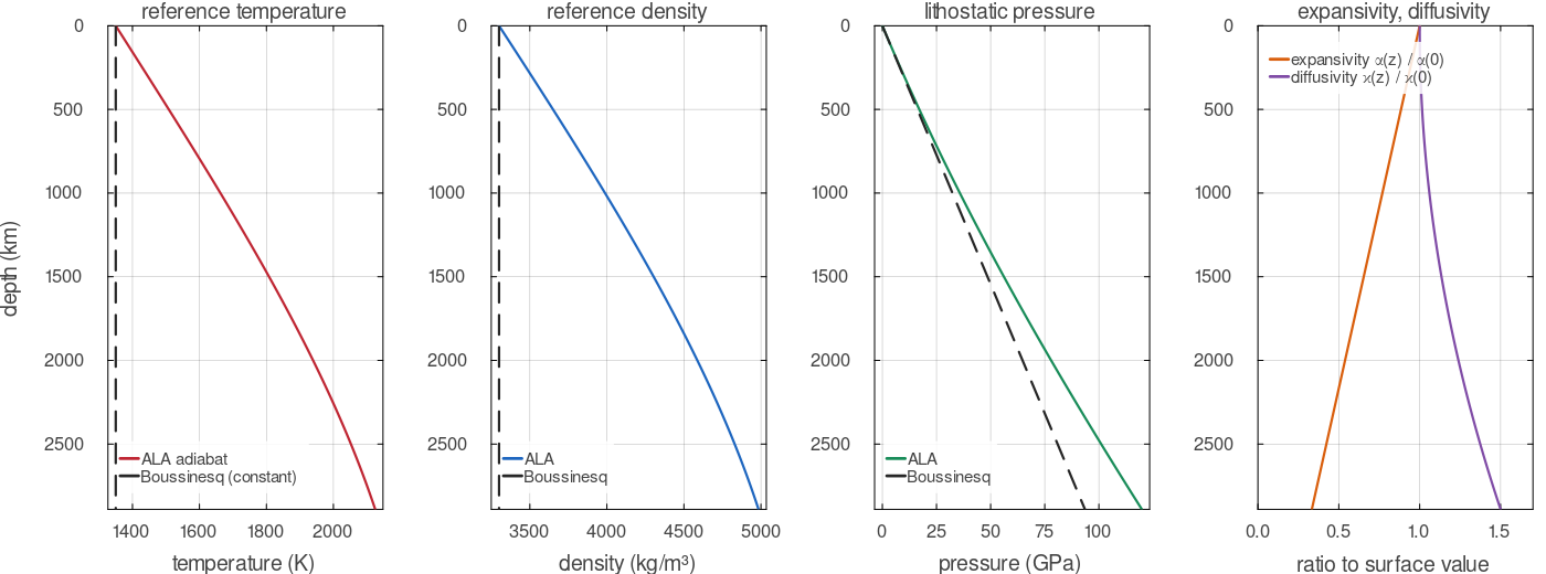
The reference state of the default shell, evaluated by compressibility, mantle_pressure and thermal_diffusivity. Under ALA the adiabat, the Adams-Williamson density and the pressure all rise with depth while the expansivity falls to a third of its surface value; under Boussinesq (dashed) temperature and density are constant and pressure is linear.
Nondimensionalisation and the Rayleigh number
MILEVA takes dimensional input. assemble_stokes converts to nondimensional variables before building the matrix, with the layer thickness
This keeps viscous coefficients of order one and the pressure coefficient of order meta.V_scale and meta.P_scale, so the rest of the code never sees the scaled variables.
The thermal Rayleigh number is not an input; it follows from the parameters,
with temp.T_cmb - temp.T_surf. A benchmark that wants a given benchmarks/hernlund_tackley_annulus.jl does with
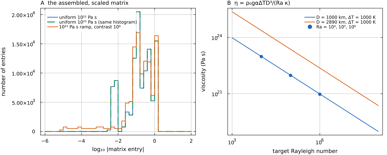
A: the magnitudes of the nonzero entries of the matrix assemble_stokes returns, on a 32 × 128 annulus. A uniform viscosity of meta.P_scale changes, from 116 Pa to 1.16 MPa); a docs/scripts/fig_governing_equations_sections.jl.
Nonlinear iteration
When the viscosity depends on strain rate, the step solves a fixed point cfg.picardTol (default cfg.picardMax sweeps. picardMax = 0 (default) means 50 sweeps when a yield law is configured and 1 otherwise. When the change stops decreasing the update is damped in cfg.useCompositeRheology); the simple Arrhenius path has no strain-rate dependence and converges on the first repeat.
Set picardMax = 1 when viscosity does not depend on strain rate
"Yield law active" means any of mat.maxYieldStress, mat.cohesion_upper, mat.cohesion_lower is finite (main_SphCon.jl), which is true for the default MaterialProperties, so on the simple viscosity path set cfg.picardMax = 1, or set those fields to Inf, to save a repeated Stokes solve per step.
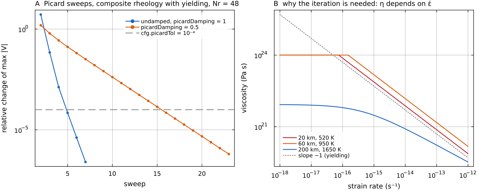
A: the nonlinear iteration of the driver, repeated here on a 48 × 192 annulus with the default composite rheology (yield law active) and a 120 km conductive lid over a plume, each sweep evaluating composite_rheology, solving Stokes, computing the strain rate and applying _picard_viscosity_update. The undamped sweep reaches picardTol in 5 sweeps, a fixed damping of 0.5 in 16. B: why the loop is needed, the composite viscosity against strain rate at three points of the lid and mantle; where the yield branch is active its slope is docs/scripts/fig_governing_equations_sections.jl.
Verifying the operator
The work-dissipation identity holds exactly for any Stokes solution at any viscosity field,
and negative tests/test_annulus_operator.jl solves a smooth load on an exponential radial viscosity ramp in the spherical annulus at tests/test_stokes_3d_variable_eta.jl records on a Yin-Yang chunk with a radial viscosity ramp:
| contrast | |||
|---|---|---|---|
| 1 | 0.9961 | 1.0026 | 1.0029 |
| 0.9880 | 0.9952 | 0.9985 | |
| 0.9909 | 0.9921 | 0.9953 | |
| 0.9812 | 0.9813 | 0.9841 |
improving with refinement at every contrast. These are internal consistency checks of the discrete operator. Comparison with published convection results is a separate matter, treated with the benchmarks.
The 3-D full-deviatoric operator is selected by cfg.useCurvatureTerms (default true); the false branch is the componentwise scalar Laplacian (tests/test_spherical_operator_nullmode.jl pins both).
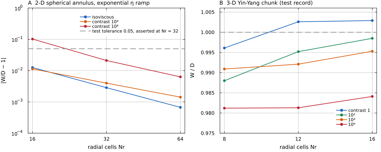
A: tests/test_annulus_operator.jl at 16, 32 and 64 radial cells; at contrast tests/test_stokes_3d_variable_eta.jl (the table above), plotted, not recomputed. Script: docs/scripts/fig_governing_equations_sections.jl.
Assumptions and simplifications
The equations above are a model of the mantle, not a complete description of it. The approximations MILEVA makes, and the reason for each, are these.
Infinite Prandtl number. Inertia is dropped from the momentum equation, which is justified by
and makes each Stokes solve independent of the previous velocity. Anelastic mass balance in 2-D, incompressible in 3-D. Under ALA/TALA the 2-D annulus solves
with a time-independent , which filters sound waves; Boussinesq runs keep . The 3-D shell keeps in every mode ( validate!warns under ALA/TALA).Buoyancy relative to a reference state. Only departures from the reference density enter
. A density change that is the same everywhere at one radius is balanced by pressure and drives no flow, so the thermal, phase and pile terms are written as lateral anomalies and the other compositional terms affect the flow only through their lateral variation. Constant gravity and heat capacity.
= cfg.gandJ kg⁻¹ K⁻¹ are the same at every depth. In a real mantle gravity varies by about ten per cent between the surface and the CMB (Dziewonski & Anderson 1981); no self-gravitation of the flow is computed. A prescribed reference state. The adiabat, density, expansivity and diffusivity are fixed functions of depth (or a table, see Material tables), not updated from the evolving mean temperature.
Viscous rock. Elastic stress memory is absent from the momentum equation; viscoelastic behaviour is approximated through an effective viscosity on its own page (Viscoelastoplastic rheology).
A fixed, flat, free-slip outer surface. Surface topography is treated separately (Free surface and isostasy).
Two dimensions in the annulus. The spherical annulus reproduces the radial weighting of a sphere, but its flow is two-dimensional, so plumes are sheets and there is no toroidal motion within the shell. The 3-D Yin-Yang shell removes this restriction at much higher cost (Hernlund & Tackley 2008).
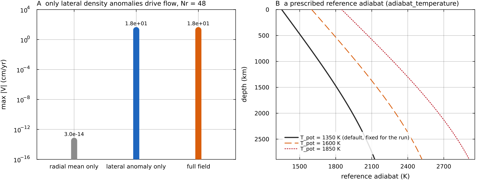
A: the blob buoyancy on a 48 × 192 annulus split into its radial mean and its lateral anomaly, each solved alone. The radial mean drives adiabat_temperature for the default T_potential_ref = 1350 K and two warmer values; the run keeps the one it starts with, whatever its mean temperature does later. Script: docs/scripts/fig_governing_equations_sections.jl.
Where in the code
| What | File, function |
|---|---|
| 2-D Stokes assembly, deviatoric operator | solvers/stokes_assembly.jl: assemble_stokes, _viscous_block_deviatoric |
| 3-D Stokes assembly | solvers/stokes_assembly_3d.jl: assemble_stokes_3d |
| metric exponent and measures | utils/geometry.jl: geometry_exponent, cell_measure, shell_measure |
| reference state | physics/compressibility.jl: compressibility, adiabat_temperature, thermal_diffusivity, anelastic_density |
| lithostatic pressure | physics/melt_phase.jl: mantle_pressure |
| strain rate and invariant | utils/compute_strain_rate.jl: compute_strain_rate |
| Picard loop, net-rotation removal, source assembly | main_SphCon.jl: main_SphCon, _net_rotation_rate |
| configuration fields | config/SimConfig.jl: geometry, dim, compressibilityMode, useDeviatoricStress, useCurvatureTerms, removeNetRotation, picardMax, picardTol |
Key references
Jarvis, G. T. & McKenzie, D. P. (1980). Convection in a compressible fluid with infinite Prandtl number. J. Fluid Mech. 96, 515-583. doi:10.1017/S002211208000225X
Hernlund, J. W. & Tackley, P. J. (2008). Modeling mantle convection in the spherical annulus. PEPI 171, 48-54. doi:10.1016/j.pepi.2008.07.037
King, S. D. et al. (2010). A community benchmark for 2-D Cartesian compressible convection in the Earth's mantle. GJI 180, 73-87. (Source of the ALA reference-state form; not used as a validation target.) doi:10.1111/j.1365-246X.2009.04413.x
Further reading
Schubert, G., Turcotte, D. L. & Olson, P. (2001). Mantle Convection in the Earth and Planets. Cambridge University Press. doi:10.1017/CBO9780511612879 The standard monograph on rheology, the governing equations, boundary-layer theory and the thermal history of the terrestrial planets.
Turcotte, D. L. & Schubert, G. (2014). Geodynamics, 3rd ed. Cambridge University Press. doi:10.1017/CBO9780511843877 Graduate textbook; derivation of the Stokes and energy equations, boundary-layer scaling of convection, mantle viscosity from post-glacial rebound.
Ricard, Y. (2015). Physics of mantle convection. In Treatise on Geophysics, 2nd ed., vol. 7, 23-71. Elsevier. doi:10.1016/B978-0-444-53802-4.00127-5 A careful treatment of compressibility, the reference state, the anelastic and Boussinesq approximations and the energy budget.
Jarvis, G. T. & McKenzie, D. P. (1980). Convection in a compressible fluid with infinite Prandtl number. J. Fluid Mech. 96, 515-583. doi:10.1017/S002211208000225X The origin of the anelastic liquid approximation for the mantle.
Gerya, T. (2019). Introduction to Numerical Geodynamic Modelling, 2nd ed. Cambridge University Press. doi:10.1017/9781316534243 Staggered-grid finite differences, marker-in-cell advection and the coupling of Stokes and energy equations, with worked examples.
Harlow, F. H. & Welch, J. E. (1965). Numerical calculation of time-dependent viscous incompressible flow of fluid with free surface. Phys. Fluids 8, 2182-2189. doi:10.1063/1.1761178 The staggered (MAC) grid.
Tackley, P. J. (2008). Modelling compressible mantle convection with large viscosity contrasts in a three-dimensional spherical shell using the yin-yang grid. PEPI 171, 7-18. doi:10.1016/j.pepi.2008.08.005 Compressible convection and large viscosity contrasts on the Yin-Yang shell.
Stacey, F. D. & Davis, P. M. (2008). Physics of the Earth, 4th ed. Cambridge University Press. doi:10.1017/CBO9780511812910 Thermodynamics of the deep Earth, including adiabats, the Grüneisen parameter, the depth dependence of expansivity and conductivity.
Dziewonski, A. M. & Anderson, D. L. (1981). Preliminary reference Earth model. PEPI 25, 297-356. doi:10.1016/0031-9201(81)90046-7 Radial density, pressure and gravity of the Earth (PREM).
Solomatov, V. S. & Moresi, L.-N. (1996). Stagnant lid convection on Venus. J. Geophys. Res. Planets 101, 4737-4753. doi:10.1029/95JE03361
Nimmo, F. & McKenzie, D. (1998). Volcanism and tectonics on Venus. Annu. Rev. Earth Planet. Sci. 26, 23-51. doi:10.1146/annurev.earth.26.1.23