Melting and crust production
Melting is computed on the markers by basalt_evolution! (physics/basalt_evolution.jl) when cfg.trackBasalt = true (default false). Each call melts supersolidus markers, extracts melt from the shallow ones, books the depletion of the residue, deposits the melt as basalt at the surface and in an intrusion band of the same column, and returns the heat that magma carries. A separate grid routine, melt_phase (physics/melt_phase.jl, cfg.useMeltingPhase), computes a grid melt fraction used for the latent heat where the marker scheme does not book it. Melting is skipped on the first step of a fresh run, when no time has elapsed. With cfg.twoPhaseFlow = true, melt_two_phase! takes the place of basalt_evolution! and the melt moves by Darcy flow (see Two-phase flow of melt and solid).
Physical background
Why the solid mantle melts
The mantle is solid on geological time scales, yet almost every rocky planet has built its crust from partial melts of it. The reason is that the temperature at which peridotite begins to melt, the solidus, rises steeply with pressure, by about 130 K GPa
The depth at which rising mantle first meets the solidus, and so the amount of melt it can make before it stops rising, is set by its temperature. The usual measure is the potential temperature
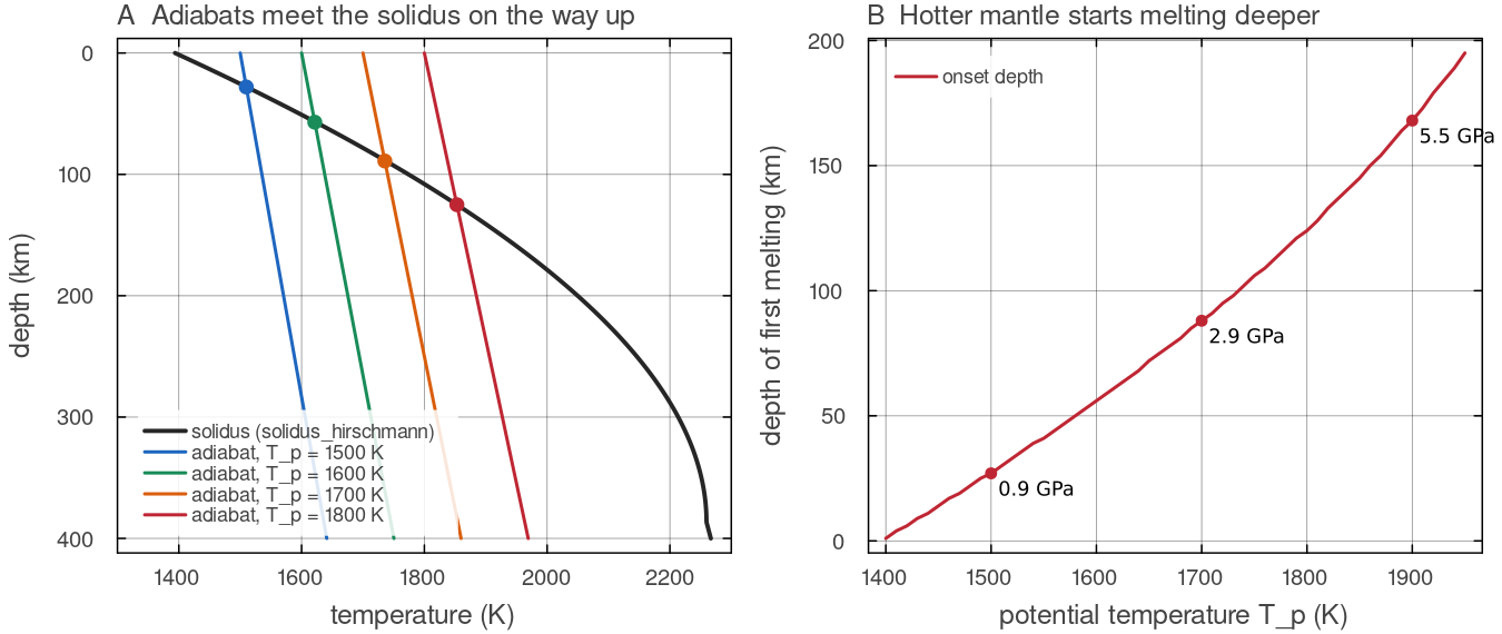
A: solidus_hirschmann and the ALA adiabats of adiabat_temperature for potential temperatures of 1500 to 1800 K, both on mantle_pressure of the default shell; the dots mark where rising mantle first meets the solidus. B: the depth of that first crossing against potential temperature, with its pressure at three points. Mantle at 1400 K does not melt on its way up; mantle at 1900 K starts melting at about 165 km. Script: docs/scripts/fig_melting_sections.jl.
Melt fraction, productivity and the fusible budget
Above the solidus a parcel is a mixture of crystals and melt. Its melt fraction
Melting does not continue indefinitely. Peridotite is a rock of several minerals, and the low-melting component, essentially clinopyroxene and the garnet or spinel that melts with it, is exhausted after some 20 to 30 per cent melting. Beyond this clinopyroxene-out point the residue is harzburgite (olivine and orthopyroxene), whose solidus is far higher (Walter 1998; Herzberg 2004). Each increment of melt that a parcel loses therefore makes the next one harder to produce. The residue left behind is depleted. It has lost its iron-rich and aluminous components and most of its water. It is therefore less dense than fertile mantle (Jordan 1978) and, because water weakens olivine, probably more viscous (Hirth & Kohlstedt 1996). Schutt & Lesher (2006) find that 20 per cent melt removal lowers the density of the residue by 0.42 to 1.14 per cent depending on pressure, so that 1 per cent of depletion has the buoyancy of a 3 to 15 K temperature increase.
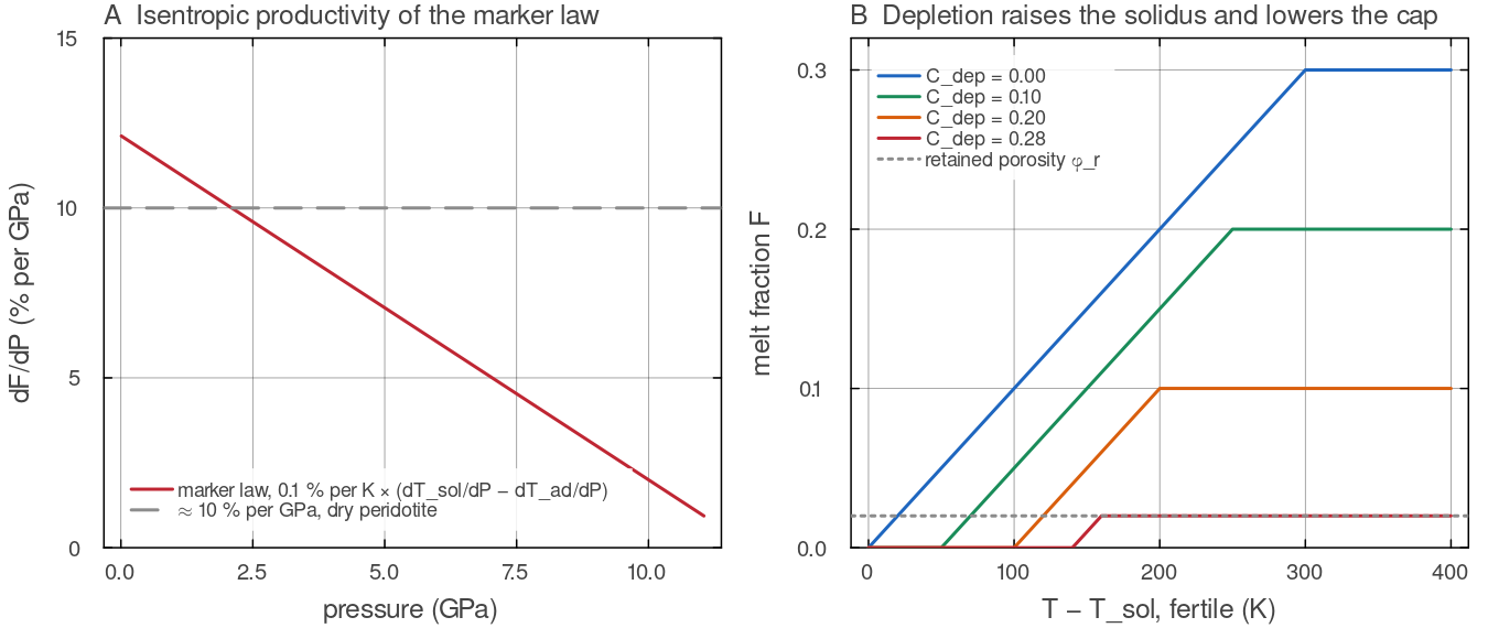
A: the isentropic productivity implied by the marker law, solidus_hirschmann and of the 1600 K adiabat of adiabat_temperature on the default shell, against the dry-peridotite value of about 10 per cent per GPa. B: the marker melt fraction against the temperature above the fertile solidus for four depletions; each increment of depletion raises the solidus (cfg.depletionSolidusRise 150 K at the full residue) and lowers the cap cfg.fertileFraction 0.30). Script: docs/scripts/fig_melting_sections.jl.
Where melt goes
Melt is less dense and far less viscous than the matrix around it, so it separates from its source by porous flow through the grain edges while the matrix compacts (McKenzie 1984). This segregation is fast compared with mantle convection, and what remains in the source is a small retained porosity of the order of a per cent. The buoyancy of melt is not guaranteed at all depths, however. Silicate melt is more compressible than the solid, so its density rises faster with pressure and approaches or exceeds that of the surrounding mantle at great depth (Stolper et al. 1981). High-pressure experiments find density crossovers for basaltic melt in the deep mantle (Ohtani & Maeda 2001) and for hydrous melt at the base of the upper mantle (Sakamaki, Suzuki & Ohtani 2006). Below the crossover, melt has no reason to rise. For Venus, Tian et al. (2023) take melt to be buoyant only above 330 km, the value MILEVA uses by default.
Melt that reaches the lithosphere either erupts as lava or intrudes, freezing in dykes, sills and plutons within or at the base of the crust. On Earth, more magma is thought to freeze at depth than reaches the surface (Crisp 1984; White, Crisp & Spera 2006). The proportion matters for the thermal evolution of a planet. Erupted magma loses its heat to the atmosphere almost at once, while intruded magma releases it within the lid, warming and weakening it (Lourenço et al. 2018, 2020).
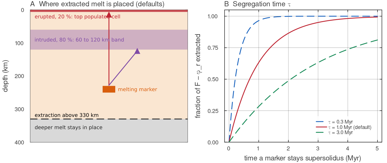
A: the default destinations of extracted melt in one azimuthal column, 20 per cent (cfg.eruptionEfficiency) erupted onto the top populated cell and 80 per cent intruded uniformly between 60 and 120 km (cfg.intrusionDepth_km), from markers shallower than cfg.meltExtractMaxDepth_km = 330 km. B: the fraction of the melt above the retained porosity that a marker loses in a given time, docs/scripts/fig_melting_sections.jl.
Why melting matters for mantle dynamics
Melting couples to convection through four channels. MILEVA represents all four in 2-D; the 3-D differences are listed below.
Composition. Melting splits the mantle into a buoyant depleted residue and a basaltic crust. Basalt that is carried below a few tens of kilometres turns into dense eclogite and can sink, while the residue tends to stay shallow. These density differences enter the momentum equation through the compositional buoyancy and can stiffen the residue through the rheology. MILEVA's default density deficit of the full residue,
cfg.depletionDensityAnomaly= 50 kg m, is 1.5 per cent of = 3300 kg m , the same order as the Schutt & Lesher (2006) values above. Heat transport. Ascending magma carries both its sensible heat and its latent heat. With
J kg and J kg K , the latent heat alone corresponds to K, so extracting 10 per cent melt from a parcel cools it by about 32 K. When a large part of a planet's heat leaves this way the regime is called a heat pipe, the dominant cooling mode of Io and proposed for early terrestrial planets (Moore & Webb 2013). Self-limitation. Because the residue melts at a higher temperature and has less fusible material left, a region that has melted once produces less melt the next time. The figure below shows the effect for a single parcel.
Heat-producing elements. Uranium, thorium and potassium prefer the melt, so melting can move the planet's radiogenic heat source from the mantle into the crust. MILEVA does this only when
cfg.radioHeatPartitionD> 0.
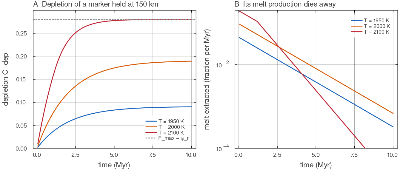
Repeated calls of basalt_evolution! (50 kyr steps, default melting parameters, Venus-sized annulus with Nr = 96, Nt = 384) on the markers of one cell held at 150 km and a fixed grid temperature of 1950, 2000 or 2100 K. The grid temperature is not updated between calls, so the parcel is not cooled by its own latent heat; the figure isolates the melting law. A: depletion rises until the depletion-raised solidus and the shrinking fusible budget leave no melt above the retained porosity; at 2100 K the parcel reaches the ceiling docs/scripts/fig_melting_sections.jl.
Typical values
| quantity | typical value | source |
|---|---|---|
| dry peridotite solidus at the surface | 1394 K (1121 °C) | Hirschmann (2000) |
| solidus slope near the surface | about 130 K GPa | Hirschmann (2000) |
| adiabatic gradient, upper mantle | 0.3 to 0.5 K km | Schubert, Turcotte & Olson (2001) |
| ambient mantle potential temperature, Earth | 1280 to 1400 °C | Herzberg et al. (2007) |
| isentropic productivity, dry peridotite | of order 10 % GPa | Langmuir, Klein & Plank (1992) |
| melting at clinopyroxene exhaustion | about 20 to 30 % | Walter (1998); Herzberg (2004) |
| residue density change at 20 % melt removal | Schutt & Lesher (2006) | |
| oceanic igneous crust, Earth | White, McKenzie & O'Nions (1992) | |
| mean crustal thickness, Venus | 8 to 25 km | James, Zuber & Phillips (2013) |
| depth above which melt is taken to be buoyant, Venus | 330 km | Tian et al. (2023) |
Symbols used on this page
| symbol | meaning | unit |
|---|---|---|
| depth below the surface and lithostatic pressure, | m, Pa (GPa where marked) | |
| grid temperature interpolated to the marker | K | |
| fertile solidus and liquidus | K | |
| solidus of a marker raised by its depletion | K | |
| depletion, the mass fraction of melt already extracted from the marker | - | |
| melt fraction | - | |
fusible fraction of the parcel, cfg.fertileFraction | - | |
solidus rise of the full residue, cfg.depletionSolidusRise | K | |
| retained porosity, below which no melt is extracted | - | |
| melt fraction extracted from a marker in one call | - | |
| segregation time and time step | s (yr in cfg) | |
| persistent weight (cell measure share) of marker | m | |
| melt-equivalent measure extracted, erupted and intruded | units of | |
| reference density, specific heat, latent heat of melting | kg m | |
| source cell, surface, intrusion band mean and receiving cell temperatures | K | |
| bulk partition coefficient of the heat-producing elements | - | |
fraction of a marker's hpe removed with its melt | - |
One step, stage by stage
Each step, every marker is asked the same questions in order. How hot is it, and at what pressure? Where is its solidus, given how much melt it has already lost? How much of it is molten, and is it shallow enough for that melt to leave? The melt that leaves makes the marker more depleted, is split between lava at the surface and intrusions at the base of the lid, and carries heat with it. The figure follows two cells of a plume head through these stages; the sections below explain each stage in detail.
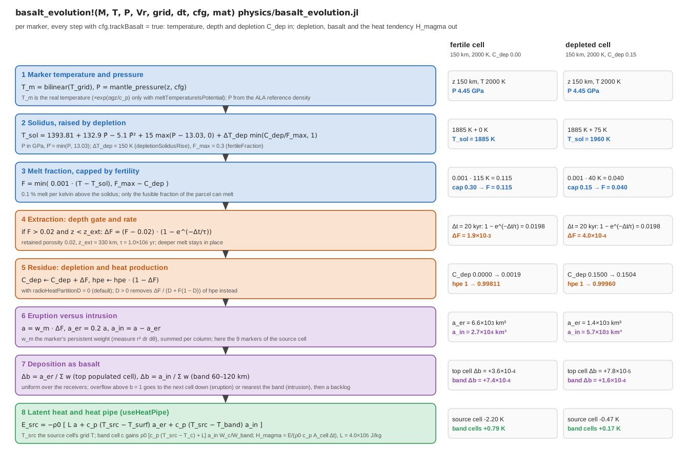
One call of basalt_evolution! with the default melting parameters on a Venus-sized annulus (Nr = 96, Nt = 384, ALA pressure, step 20 kyr, freezing term off). Right: the value each stage produces for a fertile cell (basalt_evolution! returns for those markers, receivers and cells. Script: docs/scripts/fig_melting_pipeline.jl.
Pressure
Every melting law uses one lithostatic pressure model, mantle_pressure(depth, cfg) (physics/melt_phase.jl):
| setting | |
|---|---|
compressibilityMode = "Boussinesq" | |
| ALA / TALA | |
cfg.pressureCMB_target_GPa > 0 | linearly depth-increasing density chosen so that |
The same function feeds the creep laws and the phase functions, so melting, rheology and buoyancy share one pressure.
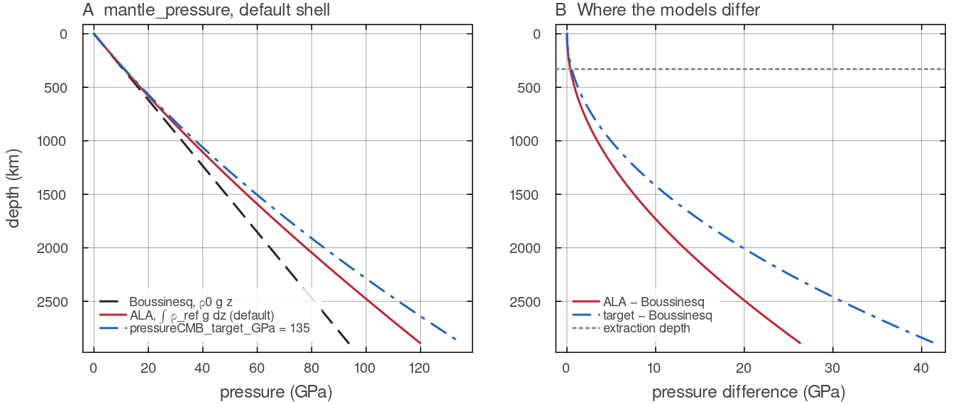
mantle_pressure on the default shell (Earth-sized, docs/scripts/fig_melting_sections.jl.
Solidus and liquidus
The fertile peridotite solidus is the Hirschmann (2000) parabola up to its peak, extended linearly beyond it (solidus_hirschmann):
The peak sits at
The liquidus, used only by the grid melt fraction, is the Andrault et al. (2011) modified Simon-Glatzel fit, floored so the melting interval is never narrower than the 600 K of dry peridotite at ambient pressure (liquidus_andrault):
Depleted residue melts hotter. On the markers the solidus rises with the fraction of fusible material already extracted:
with cfg.depletionSolidusRise (150 K at full residue) and cfg.fertileFraction (0.30).
The ramp is a simple stand-in for the change of mineralogy described under Physical background. As the fusible minerals are used up, the remaining assemblage melts at progressively higher temperature, and once config/SimConfig.jl (Maaløe 2004; Wasylenki et al. 2003).
Potential-temperature runs. In a Boussinesq run cfg.meltTemperatureIsPotential = true the solidus is compared with melt_temperature). The default false compares config/SimConfig.jl). The 3-D marker dispatch does not apply this correction.
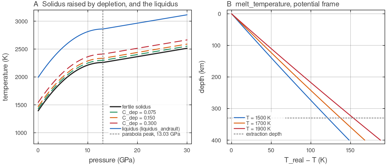
A: solidus_hirschmann for fertile mantle and raised by depletion (liquidus_andrault; the dotted line is the 13.03 GPa peak of the parabola, beyond which the linear 15 K GPamelt_temperature adds to a potential temperature when cfg.meltTemperatureIsPotential = true, on the default shell (docs/scripts/fig_melting_sections.jl.
Two melt fractions
marker law (basalt_evolution!) | grid law (melt_phase) | |
|---|---|---|
| melt fraction | ||
| used for | extraction, depletion, basalt, heat pipe | latent heat where the markers do not book it; output |
| active when | cfg.trackBasalt | cfg.useMeltingPhase |
The marker law is linear with a productivity of 0.1 % per kelvin (_MELT_PRODUCTIVITY) and a fertility cap: only the fusible component, cfg.fertileFraction of the parcel mass, can melt (the clinopyroxene-out limit; Walter 1998, Katz et al. 2003, Herzberg 2004). Basalt-bearing markers melt with the same peridotite law; there is no separate basalt or eclogite solidus. The two laws are different parameterisations, so the grid term below the extraction depth approximates the deep latent heat rather than continuing the marker law.
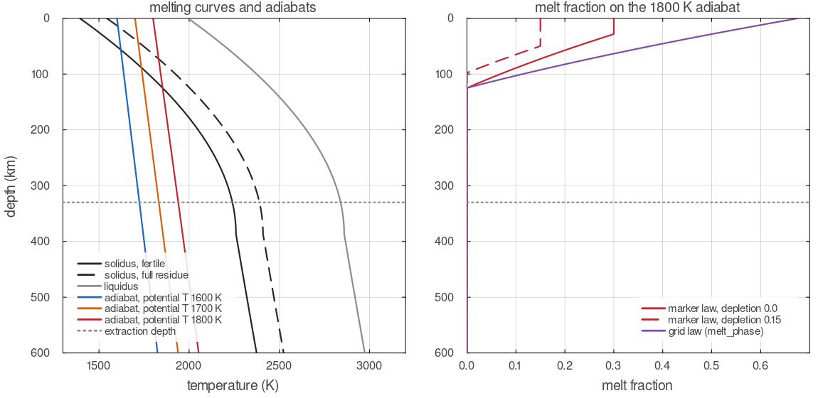
Left: solidus_hirschmann for fertile mantle and for the full residue, liquidus_andrault, and reference adiabats from adiabat_temperature, all on the shared mantle_pressure; the kink near 390 km is the 13 GPa peak of the solidus. Right: melt fraction along the 1800 K adiabat from the marker law (capped at the remaining fusible fraction) and from the grid law of melt_phase. The dotted line is the extraction depth.
Extraction
Melt above a 2 % retained porosity is removed from the marker by a prescribed segregation law, instantly with cfg.meltExtractionTime_yr = 0 and over a relaxation time otherwise. This section describes that default. With cfg.twoPhaseFlow = true (2-D spherical annulus) the prescribed law is replaced by Darcy flow of the melt through a compacting matrix. Melt is then kept as a porosity field, moves with its own velocity and freezes where it meets sub-solidus rock; see Two-phase flow of melt and solid.
Melt leaves a marker only if its melt fraction exceeds the retained porosity MELT_THRESHOLD) and the marker is shallower than cfg.meltExtractMaxDepth_km (330 km, the depth of neutral melt buoyancy on Venus used by Tian et al. 2023). Extraction relaxes the melt fraction toward cfg.meltExtractionTime_yr (1 Myr):
The amount removed per unit time is independent of the step length;
The exponential factor is the exact solution over one step of the relaxation
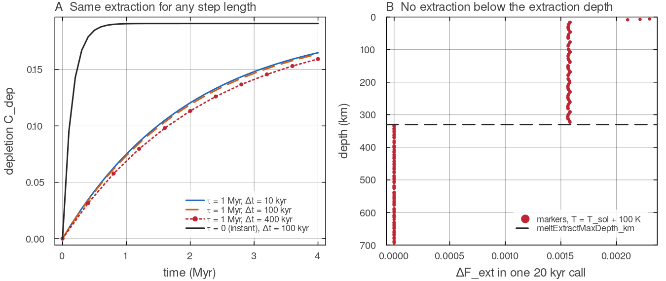
basalt_evolution! on the Venus-sized annulus (Nr = 96, Nt = 384). A: one marker cell at 150 km and a fixed 2000 K; with cfg.meltExtractMaxDepth_km keep their melt. The few markers of the top cell read a slightly higher temperature from the grid interpolation at the wall. Script: docs/scripts/fig_melting_sections.jl.
Eruption and intrusion
Extracted melt is booked as a melt-equivalent measure
| fraction | parameter | destination |
|---|---|---|
| erupted | cfg.eruptionEfficiency (0.20) | markers of the top populated cell of the column |
| intruded | the rest | markers between cfg.intrusionDepth_km and twice that depth (60 to 120 km), uniformly; if the band holds no marker, the populated cell nearest its midpoint |
With the default eruption efficiency of 0.20, the value used by Tian et al. (2023), four parts of melt are intruded for every part erupted. The melt moves vertically within its own azimuthal column, so the crust grows above the region that melted.
Deposition raises the receivers' basalt fraction. When a cell is saturated (basalt = 1) the overflow cascades into the next cell of the column (downward for eruption, outward from the band for intrusion); when the whole column is saturated the remainder is held in a per-column backlog, drained on the next call and saved in checkpoints. Nothing is discarded, and the ledger returned with every call (melt_produced, erupted, intruded, backlog, energies) closes melt_produced = erupted + intruded exactly. Eruption stamps the receivers' erupt_time, which the surface-age diagnostics use.
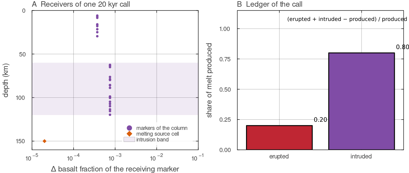
One 20 kyr call of basalt_evolution! for the fertile cell of the stage-by-stage figure above (150 km, 2000 K). A: the basalt fraction added to each marker of the column; the markers of the top populated cell receive the erupted part and the markers between 60 and 120 km the intruded part, each uniformly. B: the ledger of the call, erupted 0.20 and intruded 0.80 of the melt produced, closing to round-off. Script: docs/scripts/fig_melting_sections.jl.
Magmatic heat transport (heat pipe)
With cfg.useHeatPipe = true (default) the melt carries energy. With cfg.latentHeatMelt (
| process | source cell | destination |
|---|---|---|
| melting, all extracted melt | ||
| eruption | leaves the model (radiated at the surface) | |
| intrusion |
The sum is returned as a temperature tendency H_magma (K smelt_phase zeroes its own latent-heat term above the extraction depth so the latent heat is not counted twice, and keeps it below.
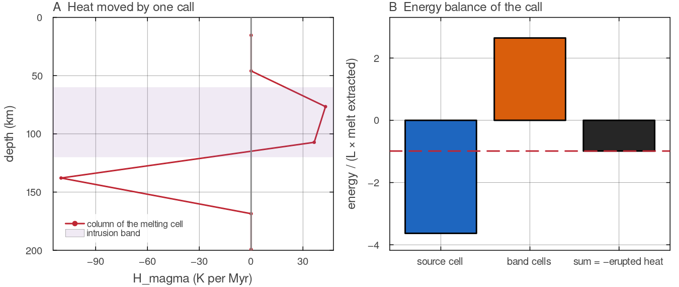
The same call as above. A: H_magma in the column, converted to K Myrbasalt_evolution! states. Script: docs/scripts/fig_melting_sections.jl.
Heat-producing elements follow the melt
Each marker carries a conserved heat-production field hpe (initially 1). With a bulk partition coefficient cfg.radioHeatPartitionD > 0, extraction of
of its hpe (batch-melting enrichment of the melt), and the removed amount is placed on the markers that received that column's basalt, in proportion to what each received. The inventory _hpe_partition_factor in solvers/diffuse_temperature.jl); see Heat sources and thermal boundaries.
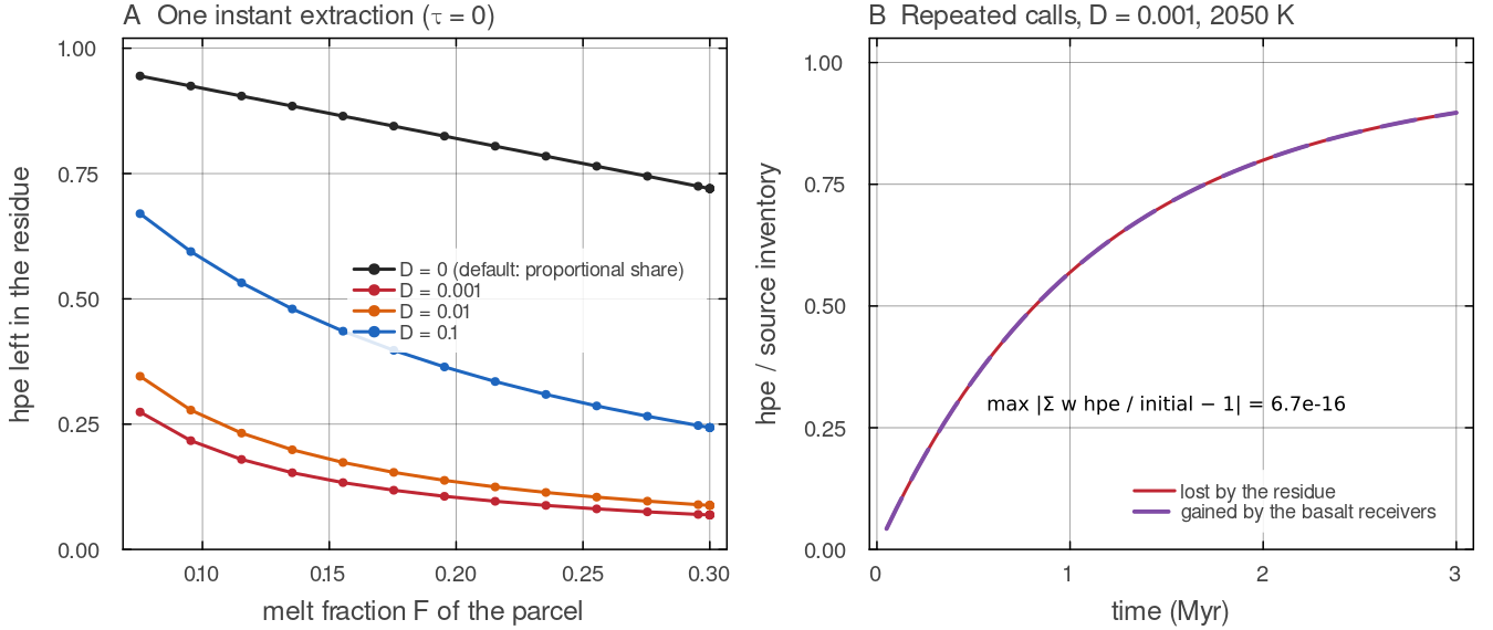
basalt_evolution! on single marker cells at 150 km. A: one instant extraction (docs/scripts/fig_melting_sections.jl.
Magma-ocean freezing term
cfg.useMagmaOceanFreezing (default true) adds basalt to every marker shallower than the eclogite transition whose temperature is below the solidus, by freezing_source). Set it false for any run whose crust should come from melting.
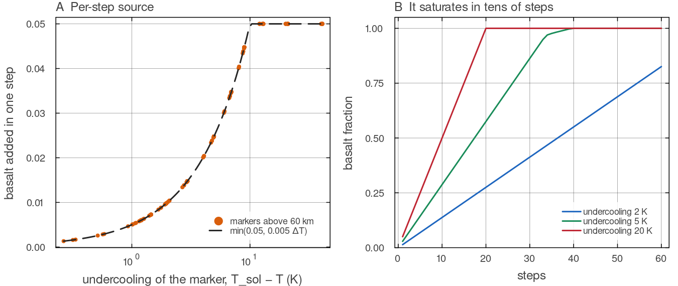
basalt_evolution! with cfg.useMagmaOceanFreezing = true on the markers above 60 km of a column held a fixed amount below the fertile solidus. A: the per-step increment of every marker against its own undercooling, which follows docs/scripts/fig_melting_sections.jl.
3-D differences
The 3-D dispatch of basalt_evolution! melts, extracts and deposits with the same laws, except that its intrusion band runs from cfg.intrusionDepth_km to five times that depth (60 to 300 km) rather than twice. It partitions hpe exactly as in 2-D. It has no heat pipe and no ledger (H_magma = nothing), and it compares the solidus with melt_phase.
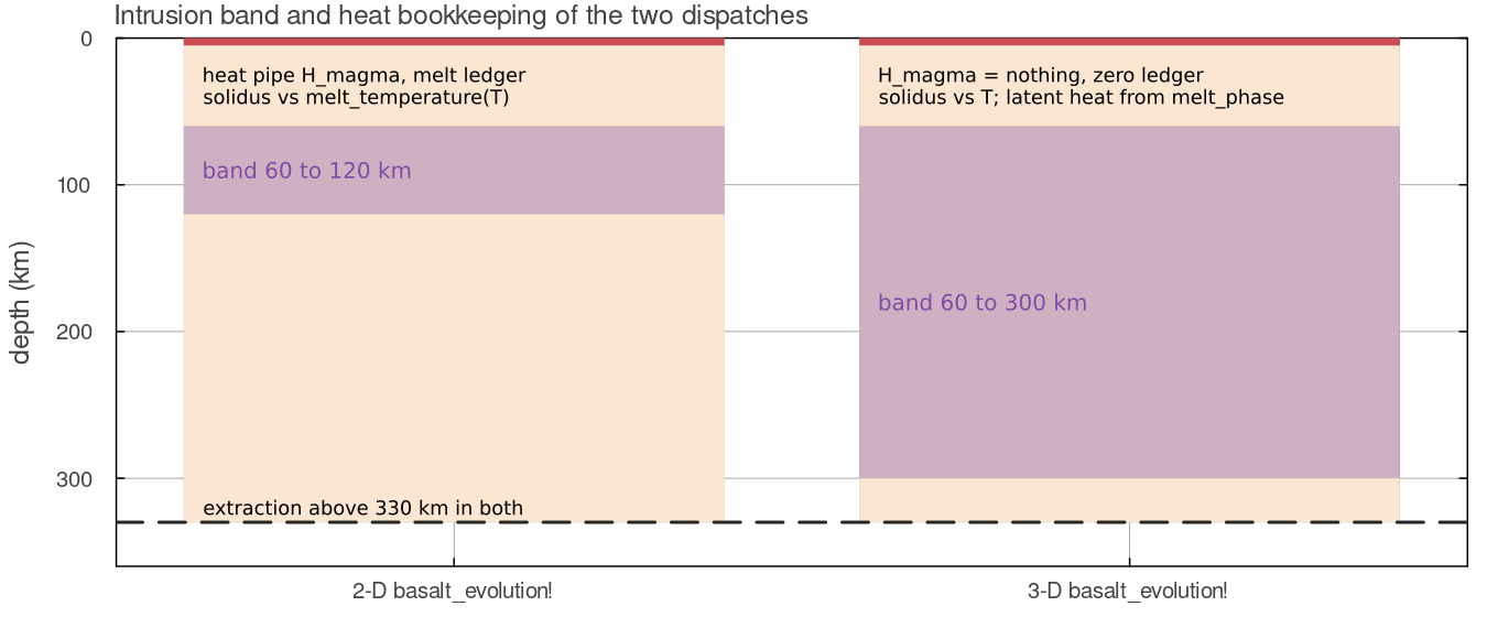
The two dispatches with the default cfg.intrusionDepth_km = 60: the 2-D band reaches twice that depth and the 3-D band five times; both extract only above 330 km. Schematic drawn from the configuration defaults. Script: docs/scripts/fig_melting_sections.jl.
Assumptions and simplifications
The melting model is a parameterisation for convection over billions of years, not a petrological model. Its main simplifications are listed here so that a result can be judged against them.
One dry lithology. Every marker melts with the dry peridotite solidus, raised only by its depletion. Basalt-bearing markers use the same law, so recycled crust does not melt earlier than peridotite as a pyroxenite or eclogite would, and water and carbon dioxide do not lower the solidus.
A linear melt fraction with a hard cap.
grows by 0.1 per cent per kelvin above the solidus until the fusible budget is used up. Real melting curves are nonlinear and slow down at clinopyroxene exhaustion (Katz et al. 2003); the cap stands for that slowdown. is evaluated from the temperature at the start of the call, and the latent heat of the extracted melt is removed afterwards through the heat pipe, so the cooling by melting acts on the next step rather than inside the melt-fraction calculation. No melt flow by default. Melt is not a separate phase. The retained porosity does not lower the density or the viscosity of its host (the grid melt fraction is used only for latent heat and output), and the extracted melt is moved within one call to the surface or to the intrusion band of its own azimuthal column. The segregation time
is a prescribed rate standing in for porous flow and dyking (McKenzie 1984). The two-phase option solves the porous flow instead. Fixed depths. The extraction limit and the intrusion band are fixed depths below the surface. They do not follow the local density crossover, the base of the lid or the thickness of the crust.
Two melt fractions. The marker law and the grid law of
melt_phaseare separate parameterisations with different liquidus assumptions, so the deep latent heat below the extraction depth is an approximation.
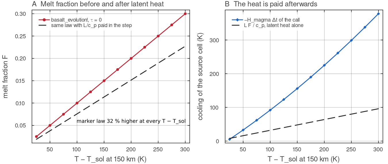
What evaluating basalt_evolution! with docs/scripts/fig_melting_sections.jl.
Scope
Crustal thickness and melt volumes depend directly on
Configuration
| field | default | meaning |
|---|---|---|
cfg.trackBasalt | false | marker melting, extraction and deposition |
cfg.useMeltingPhase | false | grid melt fraction, phase index, latent heat |
cfg.fertileFraction | 0.30 | fusible fraction |
cfg.depletionSolidusRise | 150 K | solidus rise of the full residue |
cfg.meltExtractMaxDepth_km | 330 | extraction only above this depth |
cfg.meltExtractionTime_yr | segregation time (0 = instantaneous); not read with twoPhaseFlow | |
cfg.eruptionEfficiency | 0.20 | erupted fraction |
cfg.intrusionDepth_km | 60 | top of the intrusion band (band to twice this in 2-D, five times in 3-D); not read with twoPhaseFlow |
cfg.twoPhaseFlow | false | Darcy flow of melt instead of prescribed extraction (two-phase flow) |
cfg.useHeatPipe | true | magmatic heat transport |
cfg.latentHeatMelt | latent heat of melting | |
cfg.radioHeatPartitionD | 0 | HPE partition coefficient |
cfg.useMagmaOceanFreezing | true | per-step basalt source below the solidus |
cfg.meltTemperatureIsPotential | false | compare the solidus with the real temperature |
cfg.initial_basalt_fraction | 0 | starting basalt on every marker |
cfg.pressureCMB_target_GPa | 0 | explicit pressure model |
Tests
tests/test_melt_conservation.jl: the ledger closes, nothing is discarded, and deep supersolidus markers are not extracted.tests/test_hpe_partition.jl: the partition factor and the batch-melting closure.tests/test_melt_frame.jl: the potential-temperature correction.
Key references
Hirschmann, M. M. (2000). Mantle solidus: experimental constraints and the effects of peridotite composition. G³ 1, 1042.
Andrault, D. et al. (2011). Solidus and liquidus profiles of chondritic mantle: implication for melting of the Earth across its history. EPSL 304, 251-259.
Katz, R. F., Spiegelman, M. & Langmuir, C. H. (2003). A new parameterization of hydrous mantle melting. G³ 4, 1073.
Tian, J., Tackley, P. J. & Lourenço, D. L. (2023). Icarus 399, 115539.
Lourenço, D. L., Rozel, A. B., Ballmer, M. D. & Tackley, P. J. (2020). Plutonic- squishy lid: a new global tectonic regime generated by intrusive magmatism on Earth-like planets. G³ 21, e2019GC008756.
Further reading
Crisp, J. A. (1984). Rates of magma emplacement and volcanic output. Journal of Volcanology and Geothermal Research 20, 177-211. doi:10.1016/0377-0273(84)90039-8
Herzberg, C. (2004). Geodynamic information in peridotite petrology. Journal of Petrology 45, 2507-2530. doi:10.1093/petrology/egh039
Herzberg, C., Asimow, P. D., Arndt, N., Niu, Y. et al. (2007). Temperatures in ambient mantle and plumes: constraints from basalts, picrites, and komatiites. G³ 8. doi:10.1029/2006GC001390
Hirth, G. & Kohlstedt, D. L. (1996). Water in the oceanic upper mantle: implications for rheology, melt extraction and the evolution of the lithosphere. EPSL 144, 93-108. doi:10.1016/0012-821X(96)00154-9
James, P. B., Zuber, M. T. & Phillips, R. J. (2013). Crustal thickness and support of topography on Venus. JGR Planets 118, 859-875. doi:10.1029/2012JE004237
Jordan, T. H. (1978). Composition and development of the continental tectosphere. Nature 274, 544-548. doi:10.1038/274544a0
Langmuir, C. H., Klein, E. M. & Plank, T. (1992). Petrological systematics of mid-ocean ridge basalts: constraints on melt generation beneath ocean ridges. In Mantle Flow and Melt Generation at Mid-Ocean Ridges, AGU Geophysical Monograph 71, 183-280. doi:10.1029/GM071p0183
Lourenço, D. L., Rozel, A. B., Gerya, T. & Tackley, P. J. (2018). Efficient cooling of rocky planets by intrusive magmatism. Nature Geoscience 11, 322-327. doi:10.1038/s41561-018-0094-8
Maaløe, S. (2004). The solidus of harzburgite to 3 GPa pressure: the compositions of primary abyssal tholeiite. Mineralogy and Petrology 81, 1-17. doi:10.1007/s00710-004-0028-6
McKenzie, D. (1984). The generation and compaction of partially molten rock. Journal of Petrology 25, 713-765. doi:10.1093/petrology/25.3.713
McKenzie, D. & Bickle, M. J. (1988). The volume and composition of melt generated by extension of the lithosphere. Journal of Petrology 29, 625-679. doi:10.1093/petrology/29.3.625
Moore, W. B. & Webb, A. A. G. (2013). Heat-pipe Earth. Nature 501, 501-505. doi:10.1038/nature12473
Ohtani, E. & Maeda, M. (2001). Density of basaltic melt at high pressure and stability of the melt at the base of the lower mantle. EPSL 193, 69-75. doi:10.1016/S0012-821X(01)00505-2
Sakamaki, T., Suzuki, A. & Ohtani, E. (2006). Stability of hydrous melt at the base of the Earth's upper mantle. Nature 439, 192-194. doi:10.1038/nature04352
Schubert, G., Turcotte, D. L. & Olson, P. (2001). Mantle Convection in the Earth and Planets. Cambridge University Press. doi:10.1017/CBO9780511612879
Schutt, D. L. & Lesher, C. E. (2006). Effects of melt depletion on the density and seismic velocity of garnet and spinel lherzolite. JGR Solid Earth 111, B05401. doi:10.1029/2003JB002950
Stolper, E., Walker, D., Hager, B. H. & Hays, J. F. (1981). Melt segregation from partially molten source regions: the importance of melt density and source region size. JGR 86, 6261-6271. doi:10.1029/JB086iB07p06261
Tian, J., Tackley, P. J. & Lourenço, D. L. (2023). The tectonics and volcanism of Venus: new modes facilitated by realistic crustal rheology and intrusive magmatism. Icarus 399, 115539. doi:10.1016/j.icarus.2023.115539
Walter, M. J. (1998). Melting of garnet peridotite and the origin of komatiite and depleted lithosphere. Journal of Petrology 39, 29-60. doi:10.1093/petroj/39.1.29
Wasylenki, L. E. et al. (2003). Near-solidus melting of the shallow upper mantle: partial melting experiments on depleted peridotite. Journal of Petrology 44, 1163-1191. doi:10.1093/petrology/44.7.1163
White, R. S., McKenzie, D. & O'Nions, R. K. (1992). Oceanic crustal thickness from seismic measurements and rare earth element inversions. JGR 97, 19683-19715. doi:10.1029/92JB01749
White, S. M., Crisp, J. A. & Spera, F. J. (2006). Long-term volumetric eruption rates and magma budgets. G³ 7. doi:10.1029/2005GC001002