Heat sources and thermal boundaries
This page covers what heats and cools the mantle in the energy equation, and the temperature conditions at its two walls. Diffusion and sources are solved together by diffuse_temperature (solvers/diffuse_temperature.jl) after the temperature has been advected: by the markers in 2-D by default; in 3-D the Yin patch temperature is carried by the markers as in 2-D (cfg.temperatureOnGrid is ignored in 3-D), and the Yang patch temperature is advected on the grid with the first-order advect_temperature_3d_upwind!, whatever cfg.tempAdvectionScheme says. The time discretisation is Crank-Nicolson (cfg.useImplicitTemp = true, cfg.implicitTheta = 0.5; false is explicit Euler).
The right-hand side the solver adds to the conduction term is
with reference_density (physics/compressibility.jl) that compressibility also returns.
Physical background
Where a planet's heat comes from
A rocky planet is a heat engine that is slowly running down. It formed hot, from the energy of accretion and of core formation, and it has been losing that heat through its surface ever since. At the same time the decay of long-lived radioactive isotopes of uranium, thorium and potassium keeps producing heat inside the silicate mantle and crust. The mantle therefore receives heat in three ways. It is heated from within by radioactive decay, from below through the core-mantle boundary (CMB) by a core that is itself cooling, and from its own store of sensible heat, which it gives up as it cools (secular cooling). It loses heat through the surface, where conduction across the cold outer boundary layer delivers it to the atmosphere or ocean.
For the Earth the sizes of these terms are constrained by observation. The surface heat flow is
These numbers are why the source terms on this page decide the long-term behaviour of a model. A run whose heat production exceeds what its lid can conduct away warms, and one that produces less cools. The balance shifts with time, because radioactive heating decays and the core cools, and the thermal history of a planet is the slow approach of these terms towards each other.
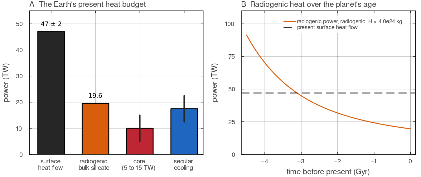
A: surface heat flow (Davies & Davies 2010), the radiogenic power of the bulk silicate Earth computed by radiogenic_H with the McDonough & Sun (1995) concentrations over docs/scripts/fig_heat_sources_sections.jl.
Radioactive decay
Each radioactive isotope decays exponentially with its own half-life. Its heat production per kilogram of rock is its concentration times the power released per kilogram of the isotope. Four isotopes matter over the age of the Solar System.
| isotope | half-life (Gyr) | share of the present heat production with MILEVA's default concentrations |
|---|---|---|
| U-238 and U-235 | 4.468 and 0.704 | 41 % |
| Th-232 | 14.05 | 42 % |
| K-40 | 1.277 | 17 % |
The half-lives are those tabulated in utils/radiogenic.jl, after Turcotte & Schubert (2002, Table 4.2), and the shares follow from those values and the default concentrations. Because U-235 and K-40 decay quickly, heat production was much larger in the past. With the default concentrations the four-isotope sum 4.5 Gyr before the time at which the concentrations hold is about 4.7 times its value at that time. A 4.5 Gyr thermal history therefore starts with a strongly heated mantle and ends with a weakly heated one. The single-rate law in MILEVA replaces the isotope mix by one effective half-life. A half-life of 2.43 Gyr, as in the pipeline example below, follows the overall decline over a planet's lifetime without resolving the change in isotope mix. Aluminium-26, with a half-life of 0.717 Myr, mattered only in the first few million years of the Solar System and is relevant only to models of planetesimals and early bodies.
Uranium, thorium and potassium are incompatible elements. Their large ions do not fit well into the crystal lattices of mantle minerals, so when rock partially melts they enter the melt preferentially. The partition coefficient
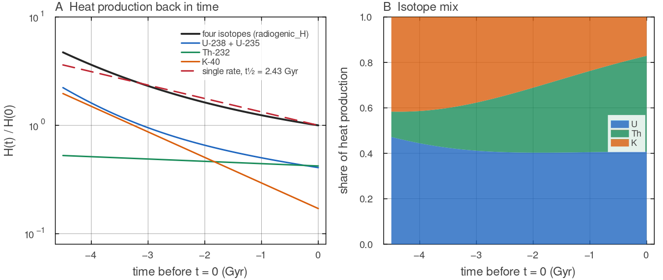
A: radiogenic_H with the default concentrations (21 ppb U, 80 ppb Th, 250 ppm K), in total and per chain, normalised by the total at _radiogenic_H0 with a half-life of 2.43 Gyr; the total is 4.7 times higher 4.5 Gyr earlier. B: the share of uranium, thorium and potassium in the total; uranium and potassium carry most of it early, thorium more than 40 per cent today. Script: docs/scripts/fig_heat_sources_sections.jl.
Internal heating and basal heating
Where the heat enters changes the character of convection (Schubert, Turcotte & Olson 2001). A layer heated from below has two thermal boundary layers of comparable strength. Hot plumes rise from the bottom boundary layer and cold sheets sink from the top one. A layer heated from within has no hot boundary layer at its base. Its interior is warm and nearly uniform, and the flow is driven mainly by cold downwellings from the top, with broad, slow return flow. Real mantles are heated in both ways, and the proportion of basal to internal heating sets how strong plumes are compared with downwellings. Two consequences follow for a model. The mean interior temperature depends on the internal heating rate, not only on the wall temperatures. And the core heat flow is not fixed in advance. It is whatever the bottom boundary layer conducts, which depends on how hot the lower mantle is.
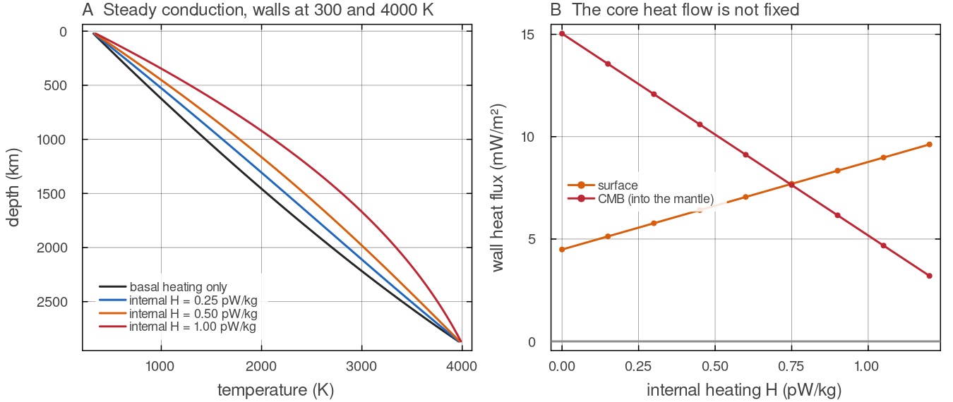
Steady states of diffuse_temperature (backward Euler, conduction only, no flow) in the default shell with the walls at 300 and 4000 K, and the wall fluxes from boundary_power. A conducting shell carries little heat, so the heating rates are far below planetary values; the picture shows the mechanism. A: internal heating bends the profile and warms the interior. B: as the interior warms, the heat flowing in from the core falls, from 15 mW mdocs/scripts/fig_heat_sources_sections.jl.
Adiabatic compression and viscous dissipation
Mantle rock is slightly compressible. A parcel that sinks is compressed by the increasing pressure and warms, and one that rises expands and cools. Without any heat exchange this gives the adiabatic temperature gradient
with
Deformation of a viscous material converts mechanical work into heat at the rate
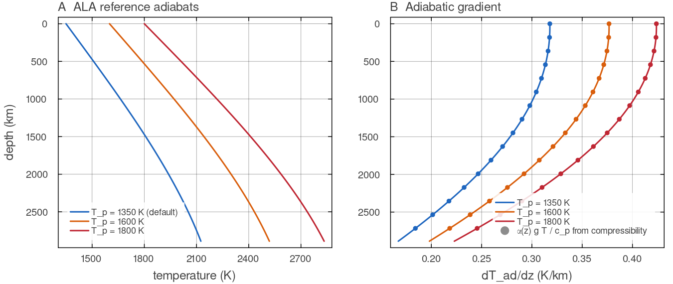
A: adiabat_temperature on the default shell (Earth-sized, compressibility returns (dots); they agree, at 0.32 to 0.42 K kmdocs/scripts/fig_heat_sources_sections.jl.
Latent heat
Melting absorbs heat and freezing releases it. The solid-state phase transitions of the mantle, olivine to wadsleyite near 410 km and ringwoodite to bridgmanite and ferropericlase near 660 km, also release or absorb latent heat as material crosses them. That heat changes the temperature of material crossing a transition and so contributes to how strongly the transition helps or hinders flow (Christensen & Yuen 1985). Rising mantle that melts is cooled by the heat of fusion, and magma that freezes at shallow depth heats its surroundings. The Phase changes and Melting pages describe these terms in full.
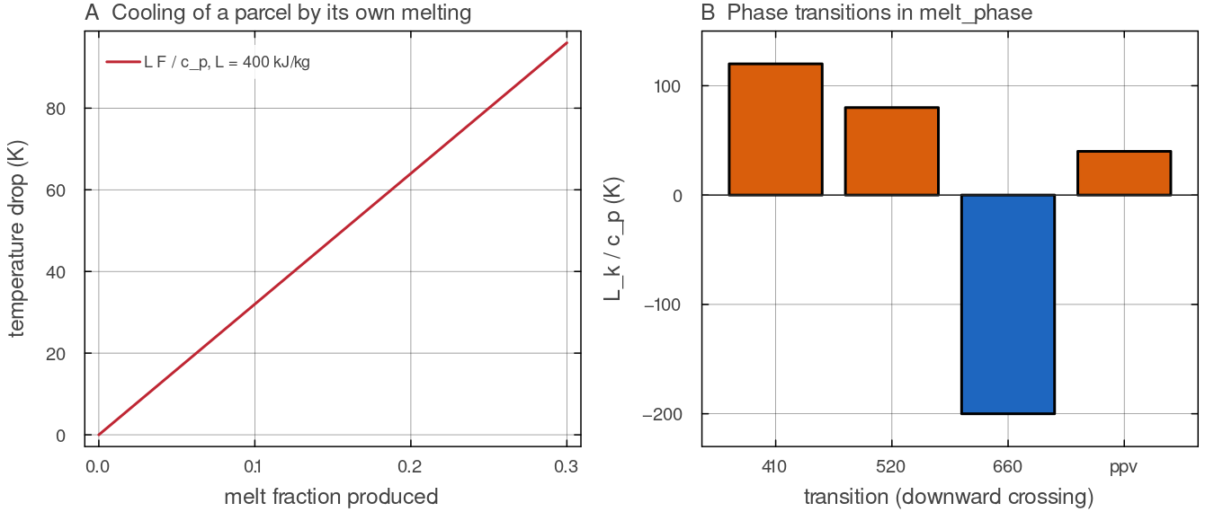
A: the cooling cfg.latentHeatMelt = 400 kJ kgmelt_phase carries, positive for the exothermic transitions that warm material crossing them downward and negative for the endothermic one near 660 km. Script: docs/scripts/fig_heat_sources_sections.jl.
The core as a heat reservoir
The core is a large reservoir of heat that the mantle draws on through its base. To first order it is a well-mixed liquid whose temperature changes only as fast as the mantle extracts heat from it. Its heat capacity is
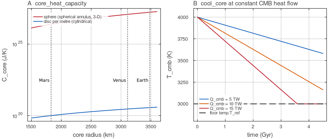
A: core_heat_capacity with the default core density and specific heat, for the spherical annulus and 3-D shell (a sphere of radius cool_core calls for the default Earth core at constant CMB heat flow; 10 TW lowers temp.T_ref after 3.6 Gyr. Script: docs/scripts/fig_heat_sources_sections.jl.
Boundary layers and wall conditions
Heat crosses the top and bottom of a convecting mantle by conduction through thin thermal boundary layers, because the flow normal to a wall vanishes there. The heat flux through a wall is
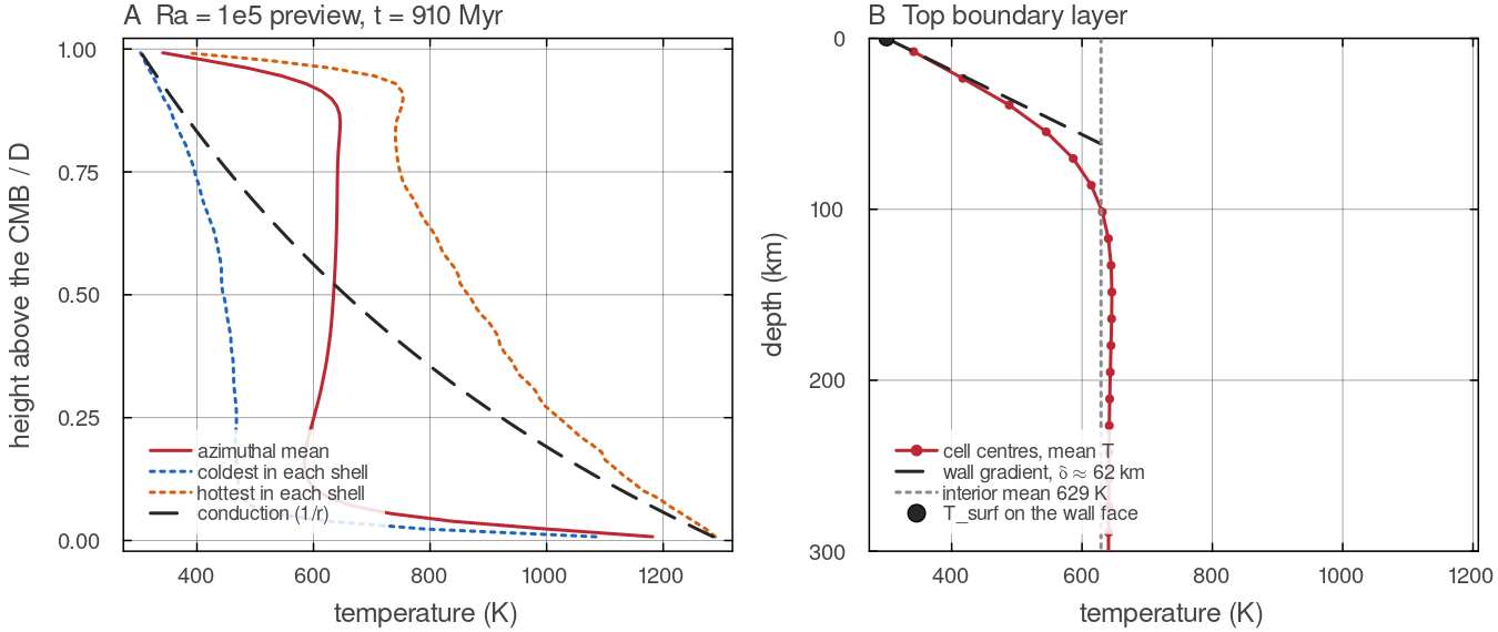
The last frame (910 Myr, 3000 steps) of the short Ra = examples/annulus_convection_2d.jl (Hernlund & Tackley 2008 shell, walls at 300 and 1300 K, Nr = 64), read from its VTK output; it is a preview, not a statistically steady state. A: the interior is nearly isothermal at 629 K and the temperature changes in thin layers at both walls, unlike the conduction profile. B: the top boundary layer cell by cell; the gradient between the wall face and the first cell centre, extrapolated to the interior temperature, gives a thickness of about 62 km. Script: docs/scripts/fig_heat_sources_sections.jl.
Typical values for the Earth and Venus
| quantity | Earth | Venus | source |
|---|---|---|---|
| surface heat flow | not measured; inferred from models and lithospheric structure | Davies & Davies (2010); Nimmo & McKenzie (1998) | |
| radiogenic heat production of the bulk silicate planet, present | about | usually assumed similar to the Earth's | McDonough & Sun (1995), with the specific heats above |
| Urey ratio | about 0.35 bulk, 0.2 convective | unknown | Korenaga (2008) |
| CMB heat flow | 5 to 15 TW | unknown | Lay et al. (2008) |
| surface temperature | MILEVA default 300 K | about 735 K | Seiff et al. (1985) |
| upper-mantle adiabatic gradient | about 0.4 K km | similar | the formula above |
Venus is close to the Earth in size and bulk composition, so its heat production is usually taken to be similar. Its surface is a single lid, with no plate tectonics today (Nimmo & McKenzie 1998). A single lid conducts heat out less efficiently than mobile plates, so for the same heat production the interior of Venus can retain more of its heat. The balance between radiogenic heating, core heat and surface loss is therefore a first-order question for Venus models.
Source terms
Each step, the code works out how fast every cell would warm or cool if no heat were conducted away, and then lets conduction redistribute that heat. The radiogenic part starts from one planet-wide rate that decays with time and is then scaled cell by cell according to what the cell is made of. Under the compressible (ALA) equations two more terms appear. Rising material cools as it expands and sinking material warms as it is compressed, and flow warms the rock it deforms. At the bottom wall the core feeds heat through the CMB face, and in the parameterised mode the core cools by exactly the heat it hands over.
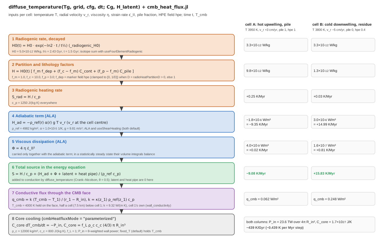
The two example cells sit in the bottom row of the default shell (docs/scripts/fig_heat_sources_pipeline.jl.
| source | switch | form | where |
|---|---|---|---|
| radiogenic, single rate | cfg.useRadiogenicHeating | _radiogenic_H0, diffuse_temperature | |
| radiogenic, four isotopes | cfg.useFourElementRadiogenic (with the above) | U-238, U-235, Th-232, K-40, Al-26 decay | radiogenic_H (utils/radiogenic.jl) |
| uniform internal heating | cfg.useInternalHeating | cfg.internalHeating_H (W kg | diffuse_temperature |
| two-layer heating | temp.useLayeredHeating | temp.H_upper above mid-depth, temp.H_lower below | diffuse_temperature |
| latent heat of melting | cfg.useMeltingPhase | melt_phase (physics/melt_phase.jl) | |
| latent heat of phase transitions | cfg.useMeltingPhase and cfg.usePhaseLatentHeat | melt_phase | |
| magmatic heat transport | cfg.trackBasalt and cfg.useHeatPipe | heat pipe, see Melting | basalt_evolution! |
| adiabatic heating | ALA and cfg.useShearHeating | compressibility, main_SphCon.jl | |
| viscous dissipation | ALA and cfg.useShearHeating | main_SphCon.jl |
All terms add. The volumetric terms are collected into one field in main_SphCon.jl (the source assembly before the call to diffuse_temperature), and every logging interval the driver prints each one as the surface heat flux it would carry, in mW m
Radiogenic heating
The single-rate law decays with half-life cfg.radioHeatingTau (years; 0 means constant) from cfg.radioHeatingH0 (default cfg.useFourElementRadiogenic = true the rate is instead
from the concentrations cfg.radio_U_ppb (21), radio_Th_ppb (80), radio_K_ppm (250) and radio_Al26_kgkg (0), with the half-lives and specific heat productions tabulated in utils/radiogenic.jl (U split 99.28 / 0.72 % between U-238 and U-235, K-40 at 0.0117 % of K). Time runs forward from the concentrations given:
The local rate (2-D) is
with cfg.radioHeatMantleFactor (1), radioHeatContFactor (10) for painted crust and radioHeatPileFactor (3) for pile material. _hpe_partition_factor): 1 when cfg.radioHeatPartitionD = 0 (default), otherwise the projected conserved marker field hpe that basalt_evolution! fractionates at extraction (see Melting). The 3-D solver applies
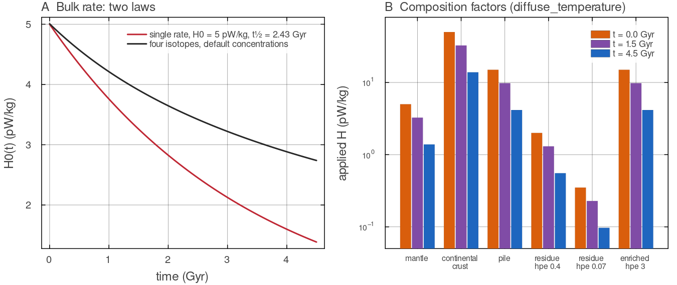
A: _radiogenic_H0 for the single-rate law (diffuse_temperature step applies to six columns of a uniform field (walls at the same temperature, so the change is the source alone), single-rate law with docs/scripts/fig_heat_sources_sections.jl.
Latent heat
The latent heat of melting on the grid, melt_phase when cfg.useMeltingPhase = true; the second needs cfg.usePhaseLatentHeat = true as well. The driver rescales them by
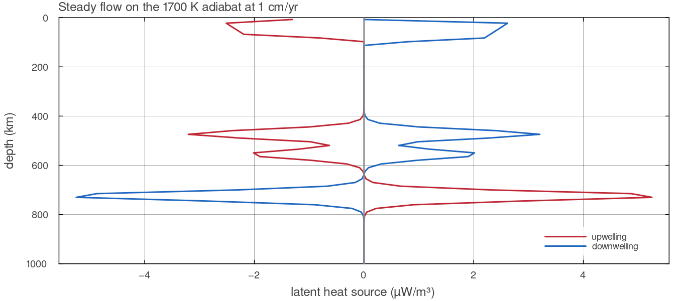
melt_phase with cfg.usePhaseLatentHeat = true on a column of the default shell (Nr = 192) on the 1700 K adiabat, with a uniform radial velocity of 1 cm yrdocs/scripts/fig_heat_sources_sections.jl.
Adiabatic heating and viscous dissipation
These are the two terms of order compressibilityMode = "ALA" and cfg.useShearHeating = true (both default). Their volume integrals balance in a statistically steady layer, so carrying one alone injects or drains the buoyancy work. TALA and Boussinesq carry neither.
In the code the adiabatic term is evaluated cell by cell as compressibility (physics/compressibility.jl) from the advected temperature of the step, so it uses the full temperature and not only the reference adiabat, and with main_SphCon.jl from the viscosity and strain rate of the step and is also written to the VTK output.
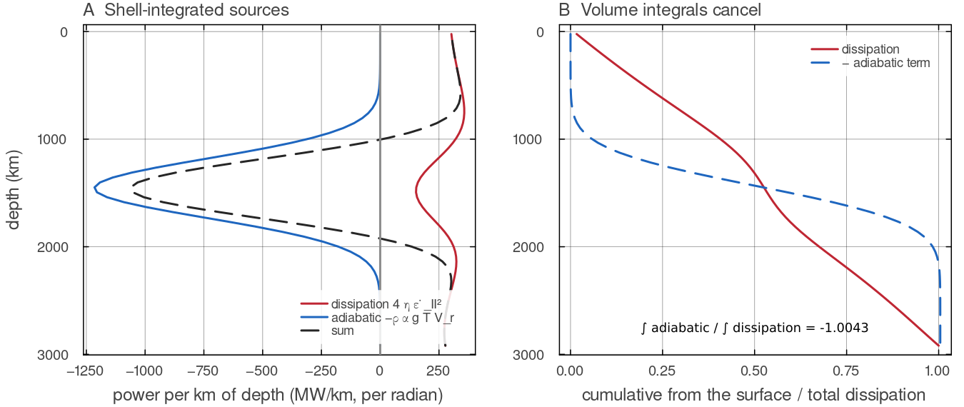
One Stokes solve (assemble_stokes, direct) on a Venus-sized spherical annulus (Nr = 64, Nt = 256, Boussinesq, isoviscous compute_strain_rate and the adiabatic term docs/scripts/fig_heat_sources_sections.jl.
Thermal boundary conditions
| wall | condition |
|---|---|
| surface | temp.T_surf (300 K default) |
| CMB | grid.T_cmb (initially temp.T_cmb) |
| azimuth (2-D) | periodic |
| 3-D Yin-Yang patch edges | Dirichlet values sampled from the other patch, cfg.nTSchwarz Schwarz sweeps per step |
The Dirichlet value lives on the wall face, not in a cell. The first and last cells are ordinary flow cells. The wall temperature enters the conduction stencil through a half-cell ghost, so the wall flux is
with wall_conductivity), and the grid advection schemes (utils/advect_temperature.jl) reflect the face value, conduction_coefficients), so the energy one cell loses through a face is the energy its neighbour gains. The wall value returned by wall_conductivity is the wall-face entry of the same coefficients, so there is one definition. The conductive reference of the Nusselt numbers (conductive_baseline_C) is the steady conduction profile of this same operator, with compute_diagnostics, cmb_conductive_flux), so the discrete energy budget closes: tests/test_nusselt_conduction.jl checks tests/test_energy_reference_state.jl checks the same under ALA with the pyrolite table on an Earth shell, together with tests/test_conduction_conservation.jl checks that the radial conduction term is an exact flux difference.
In 3-D, temp.T_cmb_patches can add Gaussian hot or cold patches to the CMB temperature (cmb_temperature_field, config/TemperatureConditions.jl); the 2-D solver uses the uniform value.
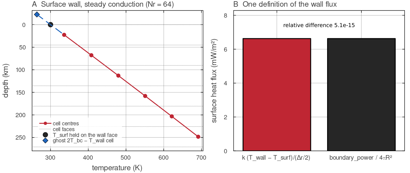
A steady conduction state of diffuse_temperature in the default shell (Nr = 64, 0.5 pW kgwall_conductivity, and the surface power of boundary_power divided by docs/scripts/fig_heat_sources_sections.jl.
Core-mantle boundary modes
cfg.cmbHeatfluxMode decides how physics/cmb_heat_flux.jl):
| mode | behaviour |
|---|---|
"fixed_T" (default) | constant temp.cmb_cooling = true it falls linearly at temp.cmb_cooling_rate K Gyr |
"fixed_flux" | cfg.cmbHeatflux (W m |
"parameterized" | the core cools by the heat it delivers to the mantle |
In the parameterised mode the core is a well-mixed sensible-heat reservoir with no inner core and no internal heating:
with cfg.coreDensity (12 000 kg mcfg.coreCp (800 J kgcfg.coreLatentFactor (1; values above 1 are a crude stand-in for latent and gravitational energy). core_heat_capacity, cmb_area): a sphere of radius cool_core, using the solver's own wall_conductivity, see the note on the CMB conductivity below). The 3-D path still debits at the start of the step.
temp.T_ref (default 3000 K) is a floor on an evolving main_SphCon refuses to start a parameterised run whose initial "fixed_flux" mode, and in "fixed_T" with temp.cmb_cooling = true, the same floor applies in cmb_heat_flux (physics/cmb_heat_flux.jl) but is not checked at start-up: a run with temp.T_ref is lifted to the floor on its first update, so lower temp.T_ref for such runs.
Under ALA the conductivity at the CMB is cmb_conductive_flux) and the wall power that debits the core (boundary_power) both read it from wall_conductivity, so the core loses exactly the energy the bottom cells gain; tests/test_energy_reference_state.jl checks this to round-off under ALA. Under Boussinesq it is the constant
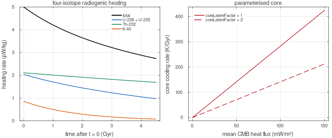
Left: radiogenic_H with the default concentrations, in total and per isotope chain. Right: the cooling rate of the parameterised core, core_heat_capacity and cmb_area for the default core, as a function of the mean CMB heat flux.
Initial temperature
temp.initial_profile selects the background (2-D marker initialisation, markers/init_markers.jl):
| value | background |
|---|---|
"adiabatic" (default) | the reference adiabat temp.tbl_top_thickness and temp.tbl_bottom_thickness. With the default thicknesses (both 0, config/TemperatureConditions.jl) the profile is a linear ramp from |
"conductive" | |
"uniform" |
On top of it the 2-D path adds warm seeds at the CMB, cfg.m_wavenumber, cfg.dT_anomaly and cfg.r_anomaly, plus seeded random noise of amplitude cfg.noise_amp that decays over 15 % of the depth. At moderate Rayleigh number several steady planforms are stable and the seeded wavenumber selects one, so state it with any result.
The 'conductive' start
The marker initialiser uses the logarithmic profile of the cylindrical annulus; the spherical-annulus profile get_initial_profile in config/TemperatureConditions.jl. The 3-D default start is a linear ramp with no lateral perturbation; cfg.m_wavenumber, dT_anomaly and noise_amp are read only by the 2-D path.
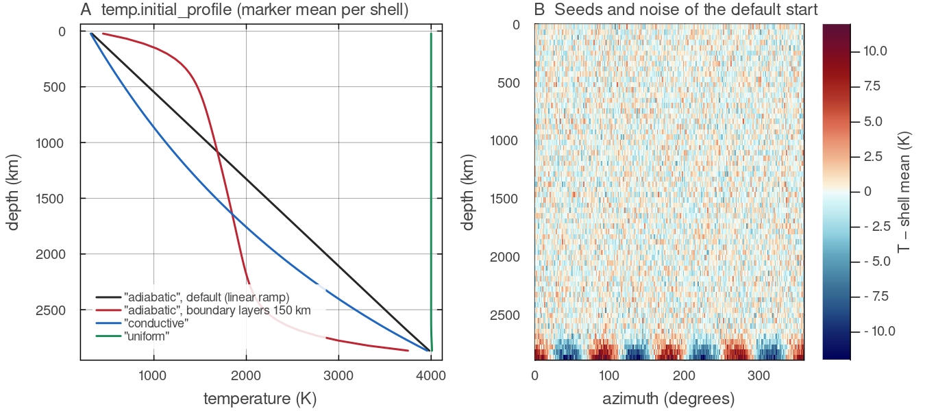
init_markers on the default shell (Nr = 64, Nt = 256), binned per shell. A: the default "adiabatic" choice with zero boundary-layer thickness is the linear ramp; with 150 km thicknesses it becomes the adiabat with exponential boundary layers; "conductive" is the logarithmic profile of the marker initialiser and "uniform" sits at cfg.m_wavenumber = 4 at the CMB (cfg.dT_anomaly = 20 K, cfg.r_anomaly = 100 km) and the 5 K noise. Script: docs/scripts/fig_heat_sources_sections.jl.
Energy budget
Every row of diagnostics.csv (utils/diagnostics_csv.jl) carries the thermal energy E_th_J thermal_energy), its rate of change dEdt_W since the previous row, the power supplied P_supplied_W (wall power plus internal heating) and budget_resid, the mismatch normalised by the larger of the surface and internal power. The wall power is accumulated every step with the diffusion solver's own boundary_power), and the internal power from what the solver actually applied (internal_power_last), so the residual tests conservation rather than sampling. Conduction conserves this measure exactly in every mode, since the operator carries conduction_coefficients). Advection conserves it too, because under ALA and TALA the 2-D Stokes solve enforces
divided by the exact cell measure, so that budget_resid reached tests/test_anelastic_mass_balance.jl). On the marker path the hand-back is exact in the mass-weighted measure delivery_scale divides the cell mass by the marker mass of the last projection), but the projection of Lagrangian marker temperatures onto the grid is not conservative, in Boussinesq runs as well, so budget_resid there measures the projection. Under ALA a marker's weight advect_markers! rescales it by budget_resid is now budget_resid contains the validate! warns). In 3-D the wall powers sum the columns of a patch with their own wall areas (wall_mean), as do the reported E_core_J, E_cmb_cum_J and budget_resid_joint extend the budget to core plus mantle. In 2-D, marker reseeding is the main operation that is not exactly conservative; it shows in budget_resid. tests/test_marker_energy.jl checks that one marker temperature step hands back exactly the energy the grid solver computed.
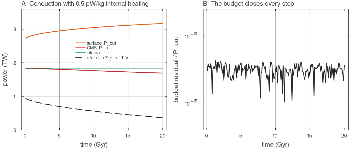
Two hundred backward-Euler steps of 100 Myr of diffuse_temperature in the default shell (Nr = 64, ALA, 0.5 pW kgboundary_power, the internal power of internal_power_last and the change of thermal_energy. B: the residual docs/scripts/fig_heat_sources_sections.jl.
Symbols used on this page
| symbol | meaning | unit |
|---|---|---|
| total source added to the conduction term, as a rate of temperature change | K s | |
| heat production per unit mass (radiogenic and uniform internal heating) | W kg | |
| planet-wide radiogenic rate after decay, before composition factors | W kg | |
half-life of the single-rate law (cfg.radioHeatingTau) or of one isotope | yr, Gyr | |
| concentration of isotope chain | kg kg | |
| lithology multipliers of the radiogenic rate | 1 | |
| heat-producing-element factor of melt depletion | 1 | |
| grid fractions of continental crust and pile material | 1 | |
| volumetric sources and sinks (latent heat, heat pipe, adiabatic term, dissipation) | W m | |
| reference density profile and constant reference density | kg m | |
| specific heat of the mantle, 1250 | J kg | |
| thermal expansivity and gravitational acceleration | K | |
| radial velocity, positive outwards | m s | |
| viscosity and second invariant of the strain rate | Pa s, s | |
| latent heats, melt fraction and phase function of transition | J kg | |
| thermal diffusivity and conductivity, | m | |
| wall temperature, surface temperature, CMB temperature | K | |
| conductive heat flux through a wall, total heat flow through the CMB | W m | |
| heat capacity and volume of the core | J K | |
| core density, core specific heat, latent-energy factor | kg m | |
| time-weighting parameter of the temperature solver | 1 |
Assumptions and simplifications
One specific heat.
J kg K everywhere, in mantle, crust and pile alike, so a given power warms every cell of the same density at the same rate. Radiogenic heating from a bulk rate. The single-rate law uses one effective half-life. The four-isotope law follows each chain separately but splits uranium and potassium with the modern U-235 and K-40 fractions at
, so concentrations meant for an early epoch carry the modern isotope ratios. Heat production differs between materials only through the multipliers , , and the depletion factor ; the 3-D solver applies alone. Fixed surface temperature.
temp.T_surfis constant in time. There is no coupling to an evolving atmosphere or climate.A simple core. In the parameterised mode the core is a single well-mixed reservoir of sensible heat with no inner core and no internal heat sources;
cfg.coreLatentFactoris the only stand-in for latent and gravitational energy. In 2-D the CMB temperature is laterally uniform.The
terms only under ALA. Adiabatic heating and viscous dissipation are carried together under ALA with cfg.useShearHeating = true, and not at all under TALA or Boussinesq, so that the energy balance between them is kept.
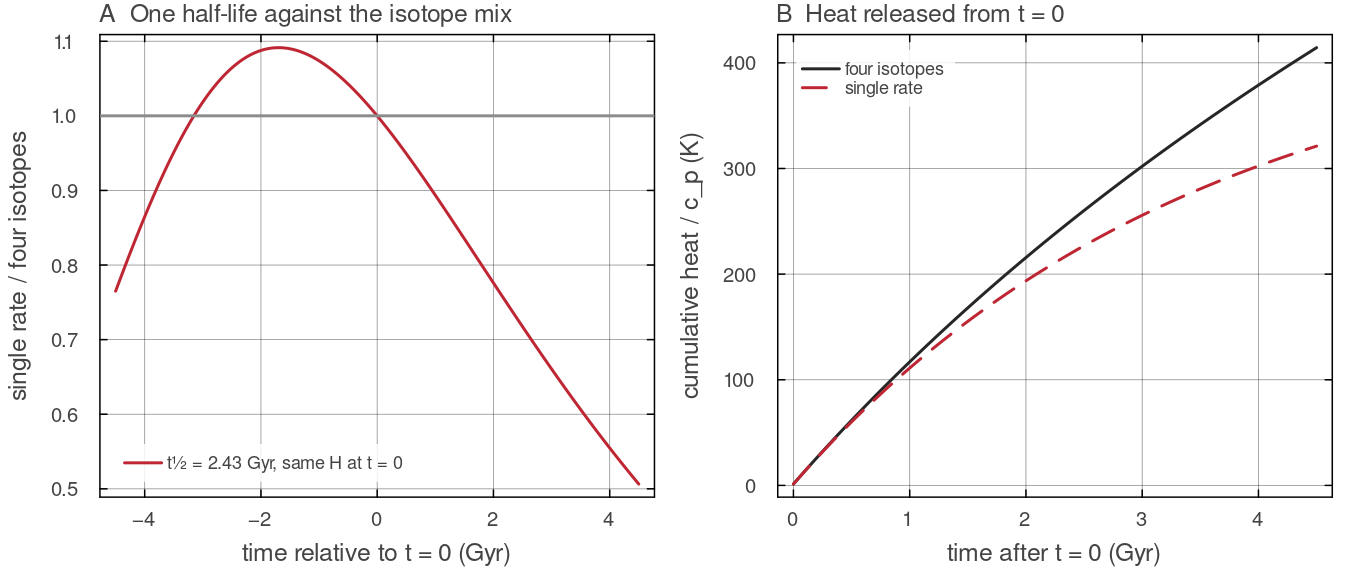
What one effective half-life does. _radiogenic_H0 for the single-rate law (docs/scripts/fig_heat_sources_sections.jl.
Configuration
| field | default | meaning |
|---|---|---|
temp.T_surf, temp.T_cmb | 300 K, 4000 K | wall temperatures |
cfg.cmbHeatfluxMode | "fixed_T" | fixed_T, fixed_flux or parameterized |
cfg.coreDensity, cfg.coreCp, cfg.coreLatentFactor | 12 000, 800, 1 | core heat capacity |
temp.cmb_cooling, temp.cmb_cooling_rate | false, 100 K Gyr | prescribed CMB cooling |
temp.T_ref | 3000 K | floor on an evolving |
cfg.useRadiogenicHeating, cfg.radioHeatingH0, cfg.radioHeatingTau | false, | single-rate radiogenic heating |
cfg.useFourElementRadiogenic | false | isotope-resolved decay |
cfg.useInternalHeating, cfg.internalHeating_H | false, 0 | uniform internal heating |
cfg.useShearHeating | true | adiabatic heating and dissipation under ALA |
cfg.useImplicitTemp, cfg.implicitTheta | true, 0.5 | time discretisation |
Key references
Stevenson, D. J., Spohn, T. & Schubert, G. (1983). Magnetism and thermal evolution of the terrestrial planets. Icarus 54, 466-489. doi:10.1016/0019-1035(83)90241-5
Turcotte, D. L. & Schubert, G. (2002). Geodynamics, 2nd ed., Table 4.2. Cambridge University Press. doi:10.1017/CBO9780511807442
Gerya, T. V. & Yuen, D. A. (2003). Characteristics-based marker-in-cell method with conservative finite-differences schemes for modeling geological flows with strongly variable transport properties. PEPI 140, 293-318. doi:10.1016/j.pepi.2003.09.006
Further reading
Christensen, U. R. & Yuen, D. A. (1985). Layered convection induced by phase transitions. Journal of Geophysical Research 90, 10291-10300. doi:10.1029/JB090iB12p10291
Davies, J. H. & Davies, D. R. (2010). Earth's surface heat flux. Solid Earth 1, 5-24. doi:10.5194/se-1-5-2010
Dziewonski, A. M. & Anderson, D. L. (1981). Preliminary reference Earth model. Physics of the Earth and Planetary Interiors 25, 297-356. doi:10.1016/0031-9201(81)90046-7
Korenaga, J. (2008). Urey ratio and the structure and evolution of Earth's mantle. Reviews of Geophysics 46, 2007RG000241. doi:10.1029/2007RG000241
Lay, T., Hernlund, J. & Buffett, B. A. (2008). Core-mantle boundary heat flow. Nature Geoscience 1, 25-32. doi:10.1038/ngeo.2007.44
Leng, W. & Zhong, S. (2008). Viscous heating, adiabatic heating and energetic consistency in compressible mantle convection. Geophysical Journal International 173, 693-702. doi:10.1111/j.1365-246X.2008.03745.x
McDonough, W. F. & Sun, S.-s. (1995). The composition of the Earth. Chemical Geology 120, 223-253. doi:10.1016/0009-2541(94)00140-4
Nimmo, F. (2015). Energetics of the core. In Treatise on Geophysics, 2nd ed., vol. 8, 27-55. Elsevier. doi:10.1016/B978-0-444-53802-4.00139-1
Nimmo, F. & McKenzie, D. (1998). Volcanism and tectonics on Venus. Annual Review of Earth and Planetary Sciences 26, 23-51. doi:10.1146/annurev.earth.26.1.23
Rudnick, R. L. & Gao, S. (2003). Composition of the continental crust. In Treatise on Geochemistry, 1-64. Elsevier. doi:10.1016/B0-08-043751-6/03016-4
Schubert, G., Turcotte, D. L. & Olson, P. (2001). Mantle Convection in the Earth and Planets. Cambridge University Press. doi:10.1017/CBO9780511612879
Seiff, A., Schofield, J. T., Kliore, A. J., Taylor, F. W. et al. (1985). Models of the structure of the atmosphere of Venus from the surface to 100 kilometers altitude. Advances in Space Research 5, 3-58. doi:10.1016/0273-1177(85)90197-8